
A static mesh is a type of mesh that cannot be deformed. It is usually used to represent static geometry within a level (ie walls, floors etc...). StaticMeshes can contain multiple levels of details which have to be manually set by the user. At runtime based on the switching method selected by the user, a specific LOD will automatically be selected based on the camera distance relative to the static mesh position in space.
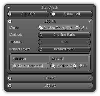
Add LOD: Add a new level of detail slot. To remove an existing LOD press the ![]() icon located on the left side of the slot box header. To set the current entry as the base mesh use the
icon located on the left side of the slot box header. To set the current entry as the base mesh use the ![]() icon. The base mesh of the will be used internally every time the physical shape of the object is required; as an example for navigation, physic collider, ray casting etc...
icon. The base mesh of the will be used internally every time the physical shape of the object is required; as an example for navigation, physic collider, ray casting etc...
Remove All: Remove all level of details and start clean.
Mesh: The mesh asset to use for the active level of detail. Click the ![]() icon to reveal the list of all mesh assets from your library. To clear the mesh asset use the
icon to reveal the list of all mesh assets from your library. To clear the mesh asset use the ![]() icon. On the right side of the control the value indicated by the
icon. On the right side of the control the value indicated by the ![]() icon display the number of references the mesh is currently associated with.
icon display the number of references the mesh is currently associated with.
Method: The method to use to dynamically select which LOD will be displayed at drawing time.
Clip End Ratio: will use the active camera distance against the static mesh object distance to determine which LOD should be used. Based on the number of LOD the static mesh contains; the system will select the LOD index corresponding to the slice the object is located relative to the camera clip end ratio. For example, if your static mesh has four LODs; and the camera clip end is set to 100m; if the object distance is 0m~25m the first LOD will be used; >25m~50m second LOD, >50m~75m third etc...Custom Ratio: Similar asClip End Ratioat the exception that you get to specify the ratio for each slice. This ratio will be used to select the LOD index. Take note that the ratio range is a value between 0.0 and 1.0 (ie 20% is 0.2).Custom Distance: This method allows you to specify the max. distance you want the LOD to be displayed. As an example, a value of 10m will indicate that if the distance between the camera and the static mesh is less than 10m this LOD index will be used etc...
- Attention
- If you choose to use one of the manual methods for selecting LOD; ensure that all your inputs are sequential to avoid popping or gaps between the distance/ratio.
Distance/Ratio: Your custom input (either distance or ratio) based on the method type you have selected.
Render Layer: For each render layer, you can set a different set of materials for each primitive. Select the active render layer by selecting an entry from the combo box. As a result, the next subsequent field will be adjusted based on the render layer selection.
Primitive: The name of the primitive within the mesh asset; to change it, enter a new name and confirm.
Material: The material that will be used to draw the primitive for the active render layer. Click the ![]() icon to populate the list of existing materials; click an entry to select. To stop using a specific material for the current primitive hit the
icon to populate the list of existing materials; click an entry to select. To stop using a specific material for the current primitive hit the ![]() icon. Located on the right side of the widget the
icon. Located on the right side of the widget the ![]() icon display how many times the material have been referenced.
icon display how many times the material have been referenced.
Preview
Please refer to the Preview help page for more information.
|
|