
The world properties page controls the settings of the physics world. To have access to this page your project needs to have selected a physics engine in the App properties.
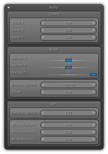
Gravity
Vector XYZ: Controls the gravity direction vector that will be applied to all physics objects, constraints and soft bodies contained in the physics world.
Water
Normal XYZ: Controls the water level normal vector; usually represented by the world space world up axis.
Density: Represents the density of the water in terms of kilograms per meter cube.
Offset: The water level position aligned using the Water normal.
Air
Density: The air density; primarily used by/and to influence lightweight soft bodies and especially aeros (also represented as kg per m3).
Wind Velocity XYZ: The wind velocity vector; also used to affect lightweight soft bodies and aeros.
Physics Settings
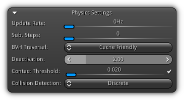
Update Rate: The optimal frame rate the physics thread should try to keep up to.
- Note
- A value of 0 let the thread run as fast as it can and does not try to keep any constant frame rate.
Maximum Steps: Numbers of steps that should be calculated on each physics frame.
Iteration Steps: For each step how many substeps should be sampled.
BVH Traversal: The type of traversal algorithm used by the physics bounding volume hierarchies (BVH).
Deactivation: The generic deactivation time to use for soft, rigid and dynamic physics expressed in seconds (1.0 = 1sec).
Contact Threshold: The minimum threshold used to invalidate a contact point when using relative breaking threshold (enabled by default). To disable relative contact breaking threshold toggle off the ![]() icon to improve the physics simulation performances.
icon to improve the physics simulation performances.
Collision Detection: Determine the type of collision algorithm. Discrete is fast but less precise; continuous is slower but more precise especially for small objects traveling at high velocities.
Collision Layers
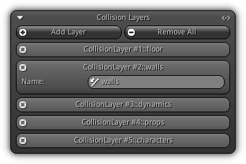
Inside your physics world, physics object is placed and organized by layers. Layers allow you to determine if a physics object should collide with other object(s) placed on another collision layer. By placing your physic objects into different layers, you can create collision rules that will result in collision masks and filters to restrict (or allow) collision between layers and the physics objects they contain.
Add Layer: Create a new collision layer.
Remove All: Delete all existing collision layer(s).
To remove an existing collision layer click the ![]() icon. To change the name of an existing layer simply type the new name and confirm the changes by pressing
icon. To change the name of an existing layer simply type the new name and confirm the changes by pressing Enter.
To automatically resolve the name of the collision layers toggle on/off the ![]() icon.
icon.
Constraint Solver
Contains the generic settings used by the internal physics constraint solver. Take note that most settings can be overridden by each physics constraint; the settings represented here are the default values the constraints will be used if no override value is specified.
Settings
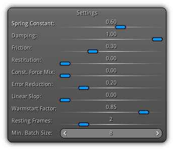
Spring Constant: The constant spring force apply on constraints.
Damping: The default amount of damping applied on constraints.
Friction: The default amount of friction to use on constraints.
Restitution: The bounciness factor to apply on constraints.
Const. Force Mix: Common CFM value to use for constraints solving.
Error Reduction: Control the ERP used for constraints solving; increase this value to avoid jittering.
Linear Slop: Additive distance factor used to calculate penetration.
Warmstart Factor: Value to warm start the constraints solving.
Resting Frames: Numbers of frames to evaluate to determine if a constraint is resting (hence its deactivation).
Min. Batch Size: How many constraints should be solved per batch.
Iterations
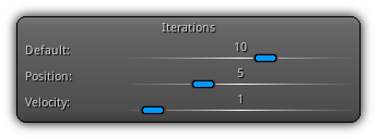
As a general rule, the higher the iterations number is the smoother constraints will behave. Higher numbers require more processing; find the perfect balance between precision and speed by tweaking each parameter to your requirements.
Default: Base amounts of iterations to apply for rigid constraints.
Position: Used by soft constraints to smoothly interpolate the positions between nodes.
Velocity: Numbers of velocity iterations used by soft bodies / aeros.
Split Impulse
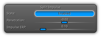
State: Determine whether or not split impulse should be used. If used it will divide the impulse into two linear components therefore increasing the fidelity of the resolved data at the cost of a slight CPU overhead.
Penetration: The penetration threshold value.
Impulse ERP: The error reduction parameter used as Baumgarte factor. A value of 0 represents no correcting force is applied and the bodies will eventually drift apart as the simulation proceeds. A value of 1 attempt to fix all joint error during the next time step (not recommended as joint error will never be completely fixed due to approximation. Recommended values are in the range of 0.1 and 0.8.
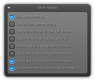
Solver Modes
| Mode | Description |
|---|---|
| Use warmstarting. | Warmstart all constraints using the default warm start value set in the Constraint Solver section to give a head start to all constraints solving at start time. |
| Use friction warmstarting. | Warmstart the friction parameter of all constraints. |
| Use bidirectional friction calculation. | Improve the constraint's friction calculations quality by splitting the incoming and released friction value. |
| Enable friction direction caching. | Improve the speed of the friction calculations at the cost of more memory. |
| Disable velocity dependent friction. | Improve the performance of constraints solving by ignoring velocity dependent friction calculation. |
| Use 3 points for area approximation. | Approximate the convex hull area of contact using 3 points instead of 4 (the default value), it is less accurate but faster to calculate and maintain. |
| Use single instruction multiple data. | Use SIMD instructions (when available on the platform) for solving constraints. Improve constraint solving speed by up to 40%. |
| Randomize the constraint solver order. | Use a non sequential pattern to progressively solve constraints. |
Debug Draw
This section is dedicated to physics visualization. Each section allow you to toggle a specific set of debugging information that will be both available during runtime and editing time.
For each section you wish to enable for debugging drawing, toggle the ![]() icon located on the right side of the header. Press it again to toggle all debugging elements contained in the section off.
icon located on the right side of the header. Press it again to toggle all debugging elements contained in the section off.
Physics Bounds
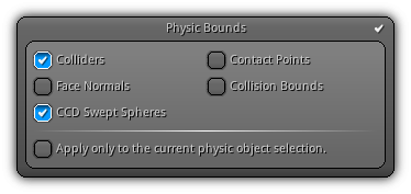
Colliders: Draw physics colliders.
Contact Points Draw contact points and their associated normal (runtime only).
Face Normals: Enable face normal debugging; especially useful when using mesh types to ensure that all normals are actually pointing the right way. Inverted normals will cause inaccurate collision behaviors.
Collision Bounds: Draw a rough representation of the internal bounds used by the physics engine to calculate collision.
CCD Swept Spheres: Draw the swept sphere of each object that will be used for continuous collision detection.
You can force debugging drawing to only be applied to the current object selection
by toggling the checkbox labeled `Apply only to the current physic object selection.`.
Physic Constraints
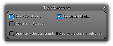
Draw Constraint: Provides visual shape feedback to constraints.
Constraint Limits: Draw the constraint limits.
Constraint Relation: Draw a dashed line between constraints that are related.
To restrict constraint drawing to the current object selection toggle the
`Draw only the constraints linked to the current selection.` option.
Soft Bodies
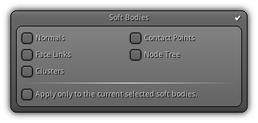
Normals: Draw the soft body face normals.
Contact Points: Only available at runtime; this option allow you to visually represent the contact point(s) of each node with the surface they collide with.
Face Links: Visually represent how the mesh faces are linked.
Node Tree: Draw the soft body node tree.
Clusters: Only available when the soft body is using clusters; this option allows you to draw the clusters used internally by the engine.
To restrict the drawing to the active soft body selection toggle the
`Apply only to the current selected soft bodies`.
|
|