
FracturedMeshes are the type of mesh to use to if you want to add destruction properties to an object. Once attached to a fracture asset with prefab chunks the mesh can then be destroyed in real time.
The set of properties that you will find in this section will allow you to control both the mesh and the fractured shards settings. The section below will allow you to pre-built the way the mesh will be destroyed so it will collide with any physical object it will shatter, explode etc...
A fractured mesh contains two different mesh stage; the first is the non-fractured mesh stage that displays the mesh in its unshattered form. This stage is basically the same as the other type of mesh that you have previously seen. The second drawing stage happens when the object starts collide with another or start shatter (due to a gunshot, an explosion or...); the system will no longer draw the mesh itself but all the shards the mesh is constructed from.
In conjunction with fracture assets (which dictate how the mesh will fracture) a fractured mesh building process happens in three steps.
- First, select the fracture asset to use as the base mesh representation.
- Setup the shell and type of slices you want to apply to the fracture which will subsequently cut the mesh into chunks.
- Generate the chunks (the actual pieces of the resulting mesh) using the slices settings set in 2. These chunks will then be converted to shards (pieces of the fractured mesh itself) which are actual physical objects connected to a chunk of the geometry.
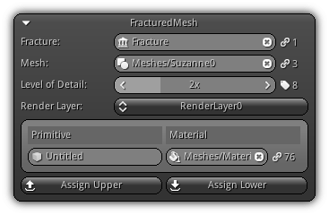
Fracture: The fracture asset to use for the active fractured mesh.
Mesh: The base mesh currently used by the fracture asset to dictate the geometric topology of the base representation of the fractured mesh(es) that uses the fracture.
- Warning
- The mesh used as a base has to be a closed mesh; meshes that are using flat normals cannot be used as each vertex have a different normal direction. Select a mesh that are using smooth normals (since the normal is shared by all connected vertices) or unique shared vertices (aka convex hull).
Level of Detail: The active level of detail (if any) to set up the subsequent material parameters.
Render Layer: The render layer to use in order to associate material to the primitive(s) of the mesh.
Primitive: The primitive name; to modify enter a new name and press Enter.
Material: The material to use for the active LOD index placed on the active render layer selected.
Assign Upper: Assign the material configuration set to all higher level of details.
Assign Lower: Assign the material presets to all lower level of details.
Preview
Please refer to the Preview help page for more information.
Fracture Settings
The fracture settings allow you to preset various parameter of the fracture asset. These settings will be shared by other resources that are connected to the same fracture. This section is divided into two areas; Shell and Slices. The shell settings allow you to specify the area surrounding the mesh where the slices will be placed as well as other hints to the underlying subsystem in charge of dealing with the actual mesh slicing.
Additionally, on top of specifying an overall shell size, another mesh can also be added at the base of the shell. This mesh is called the core mesh; before the slicing occurs this mesh will be subtracted from the base mesh allowing you to specify the inside topology of the resulting geometry. Next the slices area; this area is dedicated to the way the mesh (minus the core mesh if any) will be cut. Multiple slicing methods are available allowing you to control how the active fractured mesh will shatter, break, explode etc...
Shell
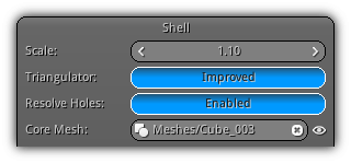
Scale: How big the shell that will be used to place the slices should be.
Triangulator: A hint allowing you to select the triangulator mode; either default or improved; check which one gives you the best results.
Resolve Holes: As the geometry get slices up holes might occurs; turning this option on will try to resolve and patch these holes based on the topology of the shell used for slicing.
Core Mesh: Specify a geometry that will be subtracted from the base mesh to (optionally) create a hollow core. To select an existing mesh from your library either enter the asset name manually or click on the ![]() icon to show the entire mesh list. To clear the mesh click the
icon to show the entire mesh list. To clear the mesh click the ![]() icon or enter an empty mesh name. The
icon or enter an empty mesh name. The ![]() located on the right side allow you to visualize the core mesh representation while being in edit mode.
located on the right side allow you to visualize the core mesh representation while being in edit mode.
Core Transform
By default when specifying a core mesh it will automatically be placed at the center of origin of the base mesh. To align and tweak the core mesh position relative to the base mesh pivot use the controls below to adjust its transformation.
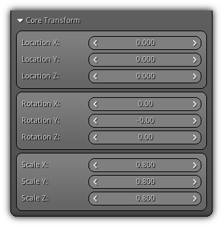
Location XYZ: The local space position of the core mesh.
Rotation XYZ: The rotation of the core mesh in local space.
Scale XYZ: The scale of the core mesh.
- Note
- In order to set the scale properly ensure that the core scale value is lower than the actual mesh to slice. Ensure that you give enough offset for the triangulator to subtract the core mesh properly. For example, a scale of 0.999 might not give enough space between the shell and the core. As a result, the triangulator will have a hard time determining which triangle is outside and which triangle is inside due to a precision issue.
Slices
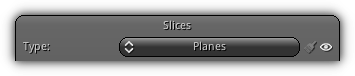
The slices section give you the opportunity to select the type of cut that you want to apply on the mesh. There are four methods of slicing available; learn more about each type in the following sections below.
Type: The type of slice; choose between Manual, Voronoi, Planes or Chips. Use the ![]() icon to toggle the visibility of the slices (in edit mode) on or off. To clear the active slices cache (wich will reset all slice specific manual settings) press the
icon to toggle the visibility of the slices (in edit mode) on or off. To clear the active slices cache (wich will reset all slice specific manual settings) press the ![]() button.
button.

Located at the bottom the section the Build Slices will update the active slices based on your current settings. To clear all active slices press Clear Slices button.
- Note
- In order to be able to visualize slices ensure that you update them first by clicking the
Build Slicesbutton located at the bottom of the section; this will allow you to have a visual representation of each slice while working on their parameters.
Manual
Allows you to manually select and place mesh(es) that will be used to slice the base mesh shell during the generation process.

This type of fracture is the most flexible but, as a downside, requires more manual setup than the others.
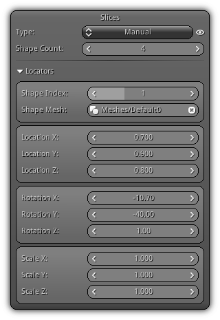
Shape Count: Increase or decrease the number of shape slots (each slot contains a single mesh that will be used to slice the base mesh).
Shape Index: The shape slot index you are currently working with.
Shape Mesh: Enter the asset name manually or use the ![]() icon to display the entire mesh list from your library. To clear the existing mesh either click the
icon to display the entire mesh list from your library. To clear the existing mesh either click the ![]() or validate an empty mesh name.
or validate an empty mesh name.
- Attention
- All shape mesh(es) that can be manually added in this section have to be closed geometry containing unique vertices.
Location XYZ: Allow you to tweak the local position of the shape mesh.
Rotation XYZ: Control the rotation of the shape mesh in local space.
Scale XYZ: Scale the shape mesh locally.
Voronoi
Ideal to simulate rocks like shattering as well as ice or glass etc...; this type allows you to allocate points inside the shell (either manually or randomly).
As a result, the shell will be split into shard-like sections that will be used to split the base mesh (minus its core if any).
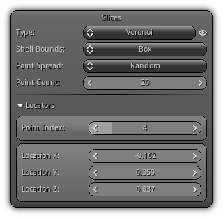
Shell Bounds: The type of bounds the shell should be using. Select between Box or Convex Hull. Box is using the object bounding box as a generic form used to encapsulate the base mesh; on the other hand, Convex Hull will follow the curvature of the base mesh and as a result, creates a more detailed silhouette of the base geometry.
Point Spread: The type of spread you are planning to use; either manual or random. Manual allows you to place the points manually inside the shell while Random is placing them arbitrarily inside the shell. Take note that changing the spread type will not reset the point position.
Point Count: The number of active points to spread inside the shell bounds.
Point Index: The active point index used to edit the location data.
Location XYZ: The location data of the active point in shell space.
Planes
Using the planes slice type you can create precise or noisy cuts using planes. This type of slice is basically acting like a knife cutting the mesh based on the plane's location within the shell mesh.
You can either place them manually, randomly or by using an even distribution where a specific number of cut(s) can be assigned on each axis.

Spread: Specify the type of distribution to use. Select between random, even or manual. As its name implies Random will shuffle all planes placing them in a random position within the shell. Even will allow you to set how many planes on the X, Y and Z axis should be generated. And finally; Manual which allow you to specify the parameters of each plane.
Base Noise: The default amount of noise to apply on newly created planes.
Base Subdiv.: The default amount of subdivision(s) to apply on newly created planes.
Plane Count: The number of planes that should be generated (only available when the spread type is set to either random or manual).
Distribution
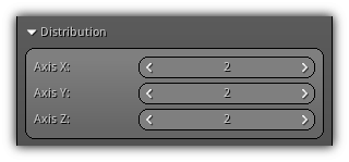
Axis XYZ: Only available when the spread is set to Even; this area allows you to specify the number of plane cut(s) that should be generated for each axis.
Rotation
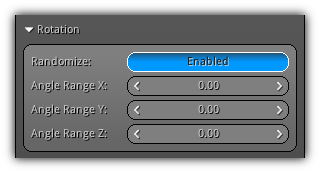
Randomize: Enable rotational randomization.
Angle Range XYZ: The random angle range for each axis (in local space). For each range the random value generated will spread from the negative to the positive axis of the value specified.
Locators
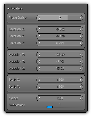
Plane Index: Specify the plane index you wish to modify its settings.
Location XYZ: The plane location in local space.
Rotation XYZ: The plane rotation in local space.
Scale XY: The active plane size on the X and Y axis.
Noise: The amount of noise to apply on each vertex of the plane.
Subdivision: The number of times the plane should be subdivided.
Chips
The slice type chips allow you to simulate dents, pucks and broken pieces.
Chips basically work the same way as planes at the exception that they are using cuboids to alter the topology of the base mesh.
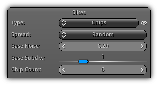
Spread: Specify the type of distribution to use. Select between random, even or manual. As its name implies Random will shuffle all chips placing them in arbitrarily within the shell. Even will allow you to set how many chips on the X, Y and Z axis should be generated. And finally; Manual which allow you to specify all parameters for each chip.
Base Noise: The default amount of noise to apply on all newly created chips.
Base Subdiv.: The default amount of subdivision to apply on newly created chips.
Chip Count: The number of chips that should be generated (only available when the spread type is set to either random or manual).
Distribution
Axis XYZ: Available when the spread is set to Even; this area allows you to specify the number of chips that should be generated for each axis.
Rotation
Randomize: Enable rotational randomization.
Angle Range XYZ: The random angle range for each axis (in local space). For each range the random value generated will spread from the negative to the positive axis of the value specified.
Scale
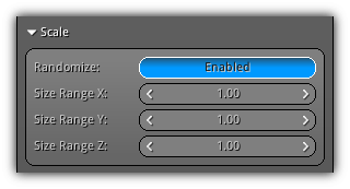
Randomize: Enable scale randomization.
Size Range XYZ: Specify the scale range to use for each axis randomization. This value will be used as a multiplier to a random range of 0 to 1 on all axis.
Locators
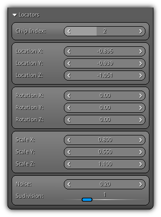
Chip Index: Select the chip index to edit.
Location XYZ: Specify the XYZ location of the chip in local space.
Rotation XYZ: Specify the chip XYZ rotation in local space.
Scale XYZ: Control the scale of the chip on all local axis.
Noise: The amount of noise to apply on each vertex of the cuboid.
Subdivision: Determine the number of subdivision that should be applied to the cube vertices.
Fracture Config
This section of the fractured mesh properties mainly focuses on setting up the physics properties that will be applied during chunks creation. Find below a complete rundown of all the properties that can be found in each area.

Similarly as for slices; to apply the settings and create the chunks press the Build Chunks button; to clear the active chunks in order to modify existing settings press the Clear Chunks button. Repeat the process to test different configuration sets.
General
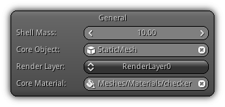
Shell Mass: The total mass of the shell. Based on this value each chunk will take a percentage of this value based on their volume contribution.
Core Object: Specify if the fractured mesh should be attached to an underlying object contained within the active scene. This object should have physic properties in order for the chunks to find an attachment point.
Render Layer: The active render layer to apply the material to.
Core Material The inner material that will be applied where the base mesh has been cut.
Core Physics
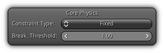
Constraint Type: Available when a core object have been specified; the constraint type represents the mechanism to use internally to connect the chunks to the core object. Select between Fixed; which is a single point constraint, Generic which is a spherical point to point constraint. The last option which is None disable the constraint creation process; chunks will not stick to the core object and will not have any constraints restraining them to the surface.
Break. Threshold: The max. breaking threshold which represents the amount of impulse that can be applied to the constraint(s) connected to the core mesh before they break. Note that, this value will be adjusted based on the mass of the chunk generated; smaller chunks will break more easily compare to big ones.
Shard Physics
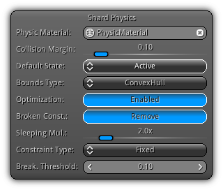
Physic Material: The physic material asset the shards will be using. To select a physic material to apply either type in the asset name or click the ![]() to display the list of all physic materials from your library. Clear the selection by entering a blank name or click the
to display the list of all physic materials from your library. Clear the selection by entering a blank name or click the ![]() icon.
icon.
Collision Margin: Add an extra distance to the shard colliders to prevent the physic object to penetrate each other.
Default State: The shards default activation state of the shard.
Bounds Type: The type of internal shape (collider) use for the shard physic object. ConvexHull is the recommended type as it is fast and precise enough; TriangleMesh is slower as it provides a collision precision on a triangle level.
Optimization: Provide an optional optimization mechanism for both ConvexHull and TriangleMesh to speed up collision (at the cost a slight overhead when building the shards collision object).
Broken Const.: Determine what to do with broken constraints. You can either choose to keep them or remove them as soon as they are broken.
Sleeping Mult.: Represent the sleeping multiplier to use to increase the deactivation process of the shards. This can be used to stabilize the shards and remove "jittering" that might occur when multiple shards of small mass or size overlap and push each other.
Constraint Type: The type of constraint to use for the shards. Select between Fixed (a simple attachment point) or Generic. That late type will create by default a strict point to point constraint, however, more functionalities can be set manually in scripts or plugin based on your requirements.
Break. Threshold: The breaking threshold value to be applied to the physic constraints generated. Take note that this value will be adjusted based on the mass of both shards that receive contacts; as a result, heavier shards will use a higher value than lighter shards.
Collision Layers
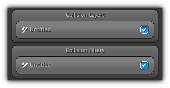
Collision Layers: Toggle on which collision layer(s) the shards will be placed on.
Collision Filter: Toggle which collision layer(s) physic objects the shards should be colliding with.
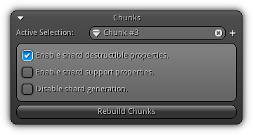
Chunks
Once the chunks are generated they will automatically be converted to shards. A shard is the actual piece of mesh (chunk) attached to a physical object. While being in View3d edit mode to select a shard first select the fractured mesh once selected any selection within the shell will select an active shard pointing to its related chunk.
Since each shard are related to a specific chunk from the original fracture asset extra properties can be toggled using the interface above.
Active Selection: The active chunks of the fractured mesh that is currently set for editing. To switch to another chunk use the ![]() icon to select the corresponding chunk in order to manipulate the flags below or simply use the
icon to select the corresponding chunk in order to manipulate the flags below or simply use the LMB to select it within a View3d (assuming that the current action is set to select see Action). To switch to the next chunk press the ![]() button.
button.
Enable shard destructible properties.: Determine whether or not the corresponding shards generated should be a static object (which is indestructible).
Enable shard support properties.: This option tells the system that if this shard get activated (or its constraint is broken) all upper-level shards resting on top of it, should gets activated.
Disable shard generation.: Do not generate a shard for this chunk; the space will remain empty and will not be included in the fractured mesh.
Rebuild all Chunks: To apply changes to the press this button which will force the system to clear and rebuild all the chunks taking into consideration the settings updated in this section.
|
|