
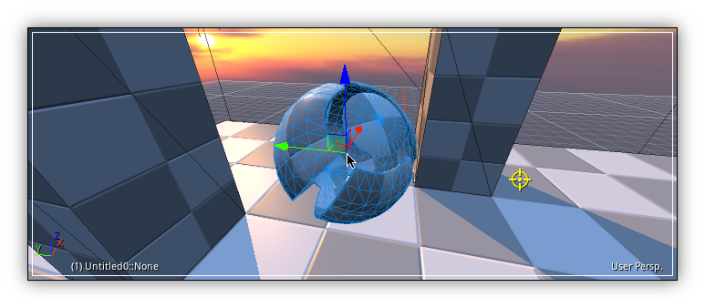
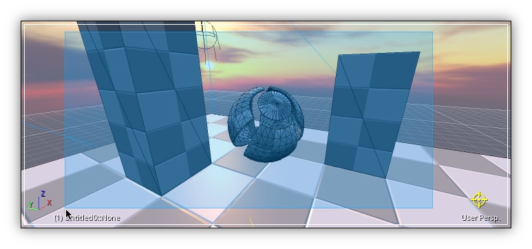
In NRGeditor the View3d is acting as a level editor and it is the core editing tool for all your scenes. Usually scenes creation start by importing assets and objects from an external COLLADA file coming from a 3d editing software like Blender, Maya, 3d Studio Max etc... Once imported you commonly start adding some render layers to create the scene composition and drawing sequence to achieve the visual look and feel that you are looking for.
In NRG the primary type of resource that you will be manipulating within this editor so as to create your worlds are objects. Objects are the base type of any 3d component active in your scene. Usually linked to assets which represent something reusable by one or multiple instances of the same or different data type.
NRG provides you with numerous resources that can be visually manipulated within the View 3d including cameras, physics, skeletons, lights, particles system, 3d text and a lot more...
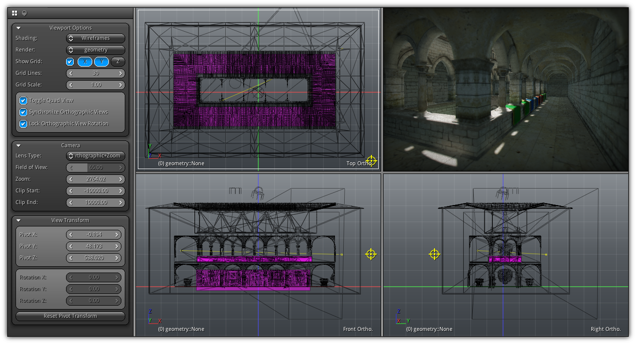
The View 3d is divided into two areas; the viewport(s) always visible and located on the right side of the editor and the tools area.
By default, when you create a new View 3d only the default 3d perspective view is visible (up right corner of the quad view). However, you can turn it into a quad view by pressing Q (like in the screenshot above) where each area can be resized independently by manipulating the edges of each area. Each viewport can draw a different render layer in orthographic, perspective or simply draw the final result of your composition (Render > Application).
The tools area (left side) allows you to switch between the standard viewport properties and the navigation tools for AI and pathfinding. Initially, the tools are docked and invisible to toggle them on/off press P. And is present for each editor inside the main menu area as an extension; the View 3d menu.
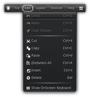
Edit
| Item | Shortcut | Action |
|---|---|---|
| Cut | Ctrl+X | Delete the active object (not selection) and keep a copy of the script to recreate them in the clipboard. |
| Copy | Ctrl+C | Generate the script to reproduce the active object and store it in the clipboard. |
| Paste | Ctrl+V | Run script previously created by a View 3d. |
| (De)select All | Ctrl+A | If all deselected; select all visible objects. If all selected; deselect all visible objects. |
| Invert | Ctrl+I | Invert the current object selection. |
| Delete | Del | Delete the current object selection but not it's attachment(s) (if any). To also remove all attachments of the selected object(s) use Backspace. |
Menu

Menu: Control the view, active selection and objects.
Action: The default action of the Left Button (or single touche).
Snap Target: Specify the type of offset the grab mode (G or V) and 3d cursor will be using when placing objects.
Manipulators: When interactive placement mode is activated (O) this area allows you to specify the type of manipulator as well as the transformation orientation.
Info.: Generic information to use as references while you are editing for you to know how many triangles, point, and lights are currently sent to the GPU per frame from the current camera location and rotation. In addition, the last section provides an indicator of the current FPS speed and sensitivity you are using which determine how fast you are moving inside the viewport.
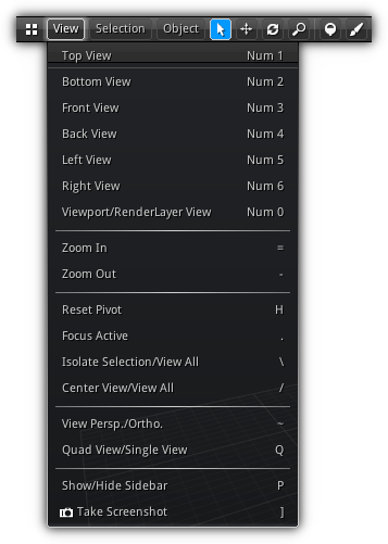
View Menu
| Item | Shortcut | Action |
|---|---|---|
| Top View | Num1 | Quickly place the viewport camera in top view. (no effect if the current viewport is rendering the full scene or is in render layer view; same apply for all other type of view). |
| Bottom View | Num2 | Quickly place the viewport camera in bottom view. |
| Front View | Num3 | Quickly place the viewport camera in front view. |
| Back View | Num4 | Quickly place the viewport camera in back view. |
| Left View | Num5 | Quickly place the viewport camera in left view. |
| Right View | Num6 | Quickly place the viewport camera in right view. |
| Viewport/Layer View | Num0 | Switch between the viewport camera or the current render layer camera (if any). Using render layer view you can control the camera using the first person view. To transfer the render layer camera position to the default viewport camera press Alt. To simply quit the render layer view mode press Num0 again. To place the current render layer camera at the same location as the default viewport press Ctrl+0. |
| Zoom In | + or Scroll Up | Increase the distance between the camera and the turntable point of interest. (available only when the viewport camera is active) |
| Zoom Out | - or Scroll Down | Decrease the distance between the camera and the turntable point of interest. (available only when the viewport camera is active) |
| Reset Pivot | H | Go back to the default viewport home position and rotation by resetting the point of interest back to (X:0,Y:0,Z:0). |
| Focus Active | . | Transfer the point of interest of the viewport camera to focus the pivot point of the active object (last object selected). |
| Isolate Selection/View All | \ | Put the point of interest of the viewport camera to look at the center of the current selection and hide all other objects that are not selected. Push \ again to get back to the previous viewport camera settings and display back all previously visible objects. |
| Center View/View All | / | Translate the point of interest of the viewport camera to be able to have view bird eye view of all objects in the scene. Please take note that depending on how large your scene is the camera can end up pretty far; make sure that the current Clip End (Viewport Properties) distance of the viewport camera is high enough to encapsulate the whole scene. |
| View Persp./Ortho. | ~ | Switch the lens type of the viewport camera between perspective (3d) or orthographic+zoom. |
| Quad View/Single View | Q | Switch the viewport between quad or single view. If you want a certain view of the quad to become active in single view mode select it by tapping it then presses this menu item or
|
| Show/Hide Sidebar | P | Toggle on/off the viewport properties. Once the properties panel retracted you can expand it back using the shortcut or by clicking on this menu item. |
| Take Screenshot | ] | Take a screenshot of the active viewport. By default the image will be saved in the path of the active project open; else it will in the current user directory. |
Selection Menu
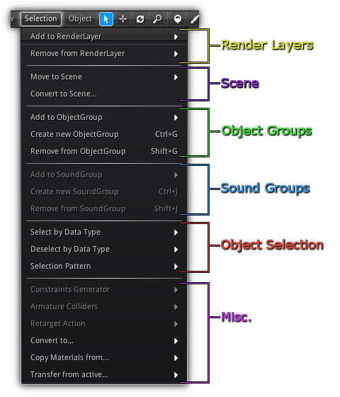
The second menu item from the view3d menu applies currently active object selection. Depending on the type of object(s) currently selected the menu will enable or disable specific items. To learn more about what you can do please refer to the different menu section below.
Render Layers
| 
|
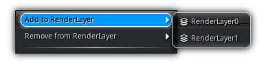
As you might already know by now to draw something on screen with NRG you need to set up your drawing sequence using Render Layers. This menu entry allows you to control on which render layer a certain object or group of objects will be associated with which render layer(s).
| Item | Action |
|---|---|
| Add to RenderLayer | Pop the list of the available render layers of your scene; selecting one an entry from the list will append the current selection to the selected render layer. |
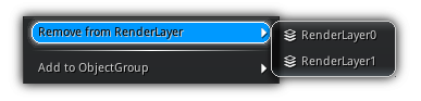
| Remove from RenderLayer | Pop the list of the available render layers of your scene; selecting one an entry from the list will remove the current selection from the selected render layer. |
Scene
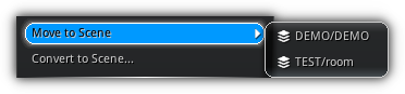
In section of the object selection menu allows you to manipulate the scene aspect of your selection. You can either move the current selected object to another scene currently loaded, or create a totally new scene based on that selection.
| Item | Action |
|---|---|
| Add to Object Group | Move the current selection to another scene currently loaded. |
| Convert to Scene... | Use the active object selection to create a new scene asset. This action will open the New Scene from Selection dialog. |
New Scene from Selection
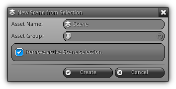
Helper dialog that allows you to convert your current object selection to a new scene asset. This scene can then be used to be loaded either statically or asynchronously across your application.
Asset Name: The name of the new scene asset.
Asset Group: The group where to place the newly created scene.
Remove active Scene selection: Force to remove the current selection from the active scene.
Create: Create a new scene asset using the active object selection.
Cancel: Cancel the operation.
Object Groups
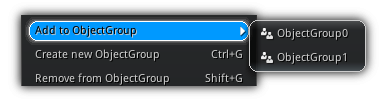
Objects can be categorized into different groups giving you the opportunity to select all objects within a specific group. While selecting an object press Ctrl and all objects contained in the same group as your selection will be selected.
| Item | Shortcut | Action |
|---|---|---|
| Add to Object Group | Move the current selection to the selected object group. | |
| Create new Object Group | Ctrl+G | Create a new object group using the current object selection. If a selected object is assigned to another group it will be transferred automatically; objects can only be part of one group. |
| Remove from Object Group | Shift+G | Remove all selected objects from their current object group (if any). |
Sound Groups
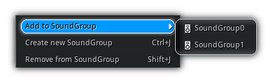
Similar as object sound sources can be added to groups. By grouping sound sources additional options are available to all the sounds associated within that group (including controlling the master gain of the sound group). To select all sound source contains within the same group as your selection hold Ctrl+Shift while selecting a specific sound source. This action will force all the sources associated with the sound group of the currently selected object to be added to the selection.
| Item | Shortcut | Action |
|---|---|---|
| Add to Sound Group | Move the current soundsource(s) selection to the selected sound group. | |
| Create new Sound Group | Ctrl+J | Create a new sound group using the current soundsource(s) contained in the current object selection. If a selected sound source is assigned to another sound group it will be automatically transferred. |
| Remove from Sound Group | Shift+J | Remove all selected sound sources from their current sound group (if any). |
Object Selection
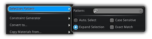
In this section of the menu, you can find tools to refine your object selections. You can either choose to select or deselect a specific data type all at once. Or search for a specific pattern contains within object names.
| Select by Data Type | Quickly select objects using their data type. Press Shift to append to the current selection. |
| Deselect by Data Type | Quickly deselect all objects already select and that belong to the selected data type. |
| Selection Pattern | Select objects using a more refine search pattern. The option Auto. Select will only select all object's name that matches the string/sub string entered in the pattern search box; while Expand Selection will append the object(s) the result of the matching pattern to the current object selection. The Case-Sensitive checkbox control if the search should make a difference or not between uppercase and lowercase object names. And Exact Match will force to only select the object that have the same name as the one entered in Pattern. |
Miscellaneous
Provides you a mixed set of tools that can be performed on the active object selection.
| Constraint Generator | Automatically create physics constraints based on the active contact points of all selected objects. Instead of creating constraints manually you can use this dialog to create them automatically; internally this is the same method used by The 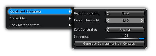
|
| Armature Colliders | Automatically creates physics colliders for the active skeletal mesh using an existing armature and its skeleton mask to generate collision bounds. First select a bounds type; choose between To select an armature; press the 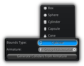
|
| Retarget Action | Transfer an action from an existing skeletal mesh to the currently active skeletal mesh. Take note that both skeletons need to have same bind pose and joints name to be able to transfer the full action successfully. 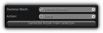
First, select the source skeletal that contains the action you wish to retarget. Press the Retarget the action by pressing the |
| Convert to... | Force an object data type to be converted to another data type. The conversion can occur in any direction (from/to) for all the following object data types: 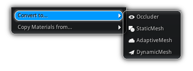
|
| Copy Materials from... | This functionality only works for the object type that can be associated with one or more materials assets. Since each "drawable" objects can have a different set of materials associated on a per RenderLayer basis; this allows you to transfer the current materials assigned to one render layer to another. 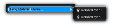
|
| Transfer from active... | Allows you to transfer 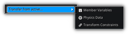
|
Object Menu
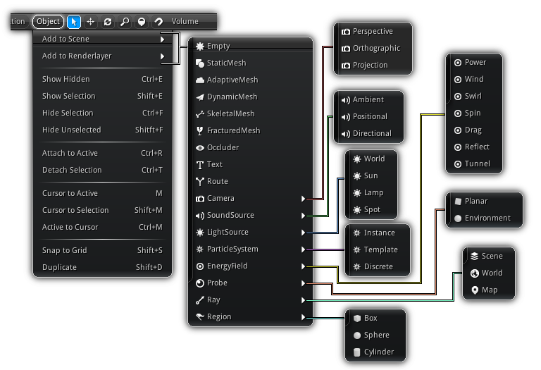
| Item | Shortcut | Action |
|---|---|---|
| Add to Scene | Add a new object to all render layers enabled in the active scene. | |
| Add to RenderLayer | Add a new object to the current active render layer. | |
| Show Hidden | Ctrl+E | Make all invisible object(s) visible. |
| Show Hidden | Shift+E | Force all selected object(s) to be visible. |
| Hide Selection | Ctrl+F | Hide all selected objects. |
| Hide Selection | Shift+F | Hide all unselected objects. |
| Attach to Active | Ctrl+R | Attach all selected object to the active object creating a parent/child relationship. |
| Attach to Active | Ctrl+T | Detach all selected objects from their parent object (if any). |
| Cursor to Active | M | Set the 3d cursor at the pivot point of the active object. |
| Cursor to Selection | Shift+M | Set the scene 3d cursor to be at the center of the current selection bounding box. |
| Active to Cursor | Ctrl+M | Set the active object location to match the current location of the scene 3d cursor. |
| Snap to Grid | Shift+S | Snap the object selection to the grid of the active viewport. (see Viewport Properties for grid settings.) |
| Duplicate | Shift+D | Clone the current object selection. |
Objects are the most common entities found into a scene. They allow you to construct the physical and visual environment that your 3d world will be using. They also allow you to implement logic blocks and triggers that will callback events to your scripts allowing you to code the core functionalities of your app. Refer to the table below to learn more about each type.
| Icon | Class | Description |
|---|---|---|
| Empty | Add an empty object to the scene that only contains transformation. | |
| StaticMesh | Create a mesh that will not be subject to any deformation. | |
| AdaptiveMesh | Create a dynamically adaptable mesh built from pre-generated LODs. | |
| DynamicMesh | Create a mesh that can be use either as a soft body or a morph target. | |
| SkeletalMesh | Create a mesh that can be deformed by a skeleton. | |
| FracturedMesh | Create a mesh that can be broken. | |
| Occluder | Create an invisible mesh that can be used to occlude others object(s). | |
| Text | Add an object that allow you to display text in 2d or 3d. | |
| Route | Routes are predefined curves that can be used to control the path of one or multiple objects. | |
| Camera | Create a camera object by selecting the type of lens you would like to use.
| |
| SoundSource | Create an sound object capable of emitting audio in 2d or 3d. | |
| LightSource | Create a new object to use as a source of light. | |
| ParticleSystem | Add a new particle system to the existing scene or renderlayer.
| |
| EnergyField | Create an attractor object that will affect physic objects and particles. | |
| Probe | Add a new probe that will allow you to capture planar and environment maps. | |
| Ray | Create a ray object that will allow you to raycast through the scene geometry, navigation maps or physic world. | |
| Region | Add a new region that will act as a trigger allowing you to filter if one or multiple objects enter, leave or are in contact with the selected region shape. |
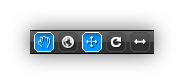
Action
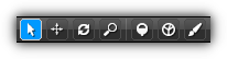
The different control mode listed below are available within each viewport only when a render layer view is activated or when the default viewport camera is active.
| Icon | Mode | Shortcut | Description |
|---|---|---|---|

| Selection | Use this mode to single or multi-select objects located on the active render layer (work when either the viewport or the render layer camera is selected). | |

| Pan | Shift+Alt+Left Button | When pan mode is selected click and drag using your left mouse button. |

| Turntable | Alt+Left Button | In turntable mode click and drag on top of any viewport in the View 3d area using your LMB. Dragging left and right will rotate the Z axis, and dragging up and down will rotate the X axis. |

| Zoom | Ctrl+Alt+Left Button | Zoom in by using your Left Button and drag up to zoom out and down to zoom in. |

| Navigation | Enter the navigation mode of the editor; this allows you to set up your scene for navigation and pathfinding. Once enabled, you can then have access to the Navigation Tools that are located on the left side property panel ( | |

| Paint | Enter the painting mode of the editor; in this mode you can create scatter brushes, vertex and texture paint or sculpt an active geometry. Paint Tools available for this more can be accessed from the left side property panel or by pressing |
- Note
- On a side note concerning the manipulators; you can increase or decrease their scale by using the
+and-; or you can manually modify the size using the Preferences dialogEditors > Manipulators.
- Warning
- On some NRG supported OS like Ubuntu and Linux Mint, the
Alt+Left Buttonshortcut is already used by the window manager. Simply append theCommandbutton to the shortcut as equivalent toAlt+Left Button. For example, to use the turntable pressCmd.+Alt+Left Button; the same apply for any other???+Alt+Left Buttoncommands and shortcuts.
Single Selection
The simplest method to select an object is to use the left click on top of it; if you are using the tablet version of the editor tap on it once. When the Shift modifier is enabled while selecting: if the object is already selected it will be deselected else it will be appended to the current selection.
To select a predefined group of objects, hold Ctrl and click on one of the objects contains within the group you are trying to select; therefore all objects that belong to that same group will automatically be selected. The same behavior applies to sound grounds. To select all sound sources within a specific group hold Ctrl+Shift. Therefore, all sound sources that belong to the same group as your selection will be selected.
For bones similar concept also apply; selecting a bone with Ctrl pressed will automatically select all connected bones.
Sometimes selecting an object when cull face is enabled requires you to step outside of the object. To turn off backface culling while selecting objects press the C key which will allow you to select from both front and back faces.
Rectangular Selection
The quickest way to select (or deselect) multiple objects in one action is to use the rectangular selection. Start by clicking where you want the rectangle to start (just like in the single selection) and drag where you want the rectangle to end; then release to select.
3d Cursor
To change the location of the 3d cursor first make sure it is enabled inside the scene properties. Then double click or tap to place it in 3d space. During this action you can also hold C (just like for selection) to disable back face culling or A to expand the picking ray to also include non-drawable objects bounds to test if the ray intersects them.
- Note
- Setting the 3d just as for single (and rectangular) selection is only available when either the viewport camera or the render layer camera is active. No selection is possible when the viewport not in editing mode.
Snap Target
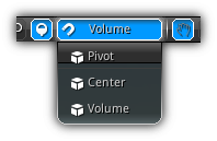
Working in conjunction with the 3d cursor and the grab mode is the snap target. The snap target allows you to place and optionally align the active object selection or newly created object to the position (and normal) pointed by the 3d cursor. To place and align your object you have three different methods available. The first one pivot; will use the geometry pivot point to place the object at the location specified by the 3d cursor. Center will use the center of its bounding box to place and orient the object and finally volume; which will use the geometry/object dimension to place the object in space.
This functionality is available when either drag and dropping mesh asset from the Library to the 3d viewport. To grab and place objects simply hold the G key or V (snap to vertex) and move your mouse/touch around the viewport; placement will occur automatically while dragging.
- Remarks
- Depending on the type of grabbing operation you wish to perform, you can hold the
Shiftkey while holdingGorVto invert theZnormal direction. Useful when dealing with ie. conical objects that by default point to the negativeZaxis including spots or emitters.
Manipulators
One of the most common operations of scene editing is to transform objects. There is basically two ways of transforming objects inside NRGeditor the first one is to simply edit the location, rotation, and scale available in the active object properties panel; or to use the interactive mode by using the various manipulator(s) to transform one or multiple objects simultaneously.
| Icon | Mode | Shortcut | Description | ||
|---|---|---|---|---|---|

| Transform Mode | O | Toggle interactive transformation (on) or manual transformation (off). | ||

| Active Space | L | Allows you to change the reference coordinate system. You can either transform the object in world space (along the world axis), or in local space (using the object's rotational space).
| ||

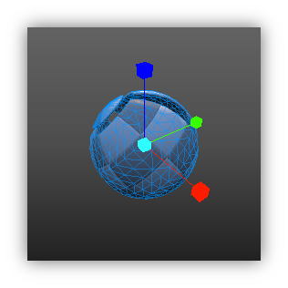
| Translate | T | Toggle the translation manipulator widget. To translate the object simply select and drag the axis arrow into the direction where you wish to move the object. Only available when the world coordinate system is enabled, the translation manipulator have three additional planes between each axis. This allows you to restrict the translation on an arbitrary 2d plane.
| ||

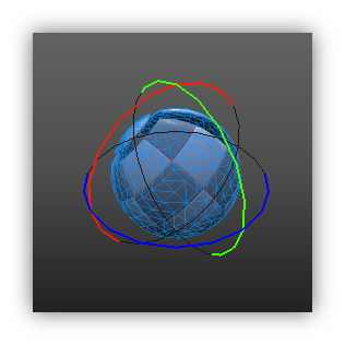
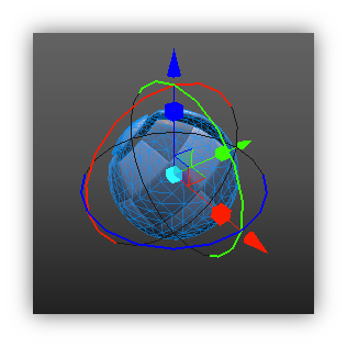
| Rotate/Revolve | R | Toggle the rotation manipulator widget. In the case multiple objects are selected you can alternatively hold Ctrl on your keyboard which will change the rotation manipulator into the "revolve" manipulator. In revolve mode all selected objects will gravitate around the center point of the selection. | ||

| Scale | S | Toggle the scale manipulator widget. On top of the three basic axis, the scale manipulator provide at its center another functionality that allows you to scale equally on all axis at once. |
- Note
- To increase or decrease the size of the manipulator while a viewport is active you can use
+or-, alternatively, you can set the manipulator size manually underPreferences > Editors > Manipulators > Size. In addition to prevent the editor to clear the velocity and force of a physics object press 'V' while dragging any of the manipulators.
Combining Manipulators
Manipulators can also be combined to form a more complex widget that allows you to have more flexibility while using the interactive transformation mode. To combine one or more manipulators simply hold the Shift key while pressing on the different mode located at the top of the 3d view.
 |
 |
 |
|
Editing Skeletons
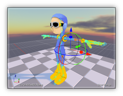
The view3d also contain another type of edit mode different from the one you've seen so far. This mode only applies to skeletal meshes that have a skeleton attached to them. To edit the transformation of an existing bone contained in a skeleton first select a skeletal mesh to be active.
Once a skeletal mesh is an active object all the bones connected to the skeleton will be highlighted and draw on top of its associated mesh (if any). You can then start selecting one or multiple bones and use the manipulators to change their local or relative transformation.
Using the pose mode you can either create new skeletal animation sequences or edit existing ones. By default, all transformation is done using forward kinematics, but using transformation constraints on one or multiple bones you can also use inverse kinematics. To exit the pose mode simply click outside the skeleton area or on another object to select it. For more information about animation curves and to learn how to create, remove, tweak and optimize existing actions please refer to the Timeline Editor manual.
FPS View
On top of the mode listed above at any time when a viewport camera or a render layer camera is active, you can use the first person mode. There are basically two ways to access it:
Right Button: Quickly toggle the first person view using the mouse right button. Take note as soon as you release the right mouse button you'll automatically get back to the regular viewport controls.
Caps Lock: Enable/disable the first person view. Depending on the scale of your scene you might want to adjust the default walking and view speed of the first person camera to do this simply access the Preferences.
Once in first person view use your mouse to control the direction of the camera view and your keyboard to control the movement direction. Refer to the table below for the key list and their action.
- Note
- For users that are using the tablet version of the editor you can emulate the
Right Buttonby tapping the screen three times in a row (3 taps).
Controls
| Key | Action |
|---|---|
| W or Up | Moves the camera forward. |
| S or Down | Moves the camera backward. |
| A or Left | Moves the camera left. |
| D or Right | Moves the camera right. |
| R or Page Up | Moves the camera up. |
| F or Page Down | Moves the camera down. |
| X | Increase the camera field of view. |
| Z | Decrease the camera field of view. |
- Note
- Depending on the dimensions of your scene the movement might seem extremely slow (or extremely fast). You can adjust the speed of your movements by tweaking the
Preferences > Editors > View 3d > FPS Speed & FPS Sensitivityproperties located under the Preferences dialog.
Adjusting Speed
While a viewport in selected you can change the walking speed using the following: Ctrl+Scroll Up/Down and the view sensitivity using Shift+Scroll Up/Down. In addition, you can use your keyboard to perform the same operation as above using the Ctrl++/- or Ctrl+Shift++/- shortcut.
Performance HUD
To enable, disable or cycle through the different modes of the Performance HUD (aka. Profiler) you can use Shift+Tab. If the profiler is Off the first press will toggle it On and enable the default profiler mode (Cpu); if the profiler is already running any subsequent press will cycle through the different profiler mode. When the last mode is selected and the viewport receive another press it will toggle Off the profiler.
SideBar
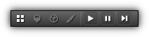
The sidebar is located on the top left area of the View3d; it allows you to change the active Mode of the View3d. You can either select the Viewport Properties by pressing the ![]() icon; or the
icon; or the Navigation Tools by selecting the ![]() button, the
button, the Partition Tools are accessible under the ![]() and the
and the Paint Tools using the ![]() . Based on the
. Based on the Mode you've selected the SideBar display will automatically be adjusted.
| Item | Description |
|---|---|
| View the active Viewport Properties. | |
Toggle the Navigation Tools. Take note that the active Action need to be set to Navigation as well in order to get control of the tools. | |
Toggle the World Partition Tools. In order to operate in this mode the active Action as to be set to Partition as well to enable the tools. | |
Access the Paint Tools. An addition to a valid mesh selection the active Action needs to be set to Paint to gain controls of the tools. | |
| Start increasing the application playback time; press again to stop and reset it back to 0. | |
| Pause the playback. | |
| Increase the time step of one frame (see Playback Controls to setup a specific or relative frame time). |
Viewport Properties
The viewport properties are located on the left side of the View 3d (you can open them up if not visible either pressing P on your keyboard or by selecting from the View 3d menu View > Show/Hide Sidebar. Once the sidebar is visible, click on the View 3d viewport properties icon ( ![]() ) to display the active viewport properties.
) to display the active viewport properties.
Options
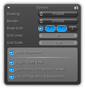
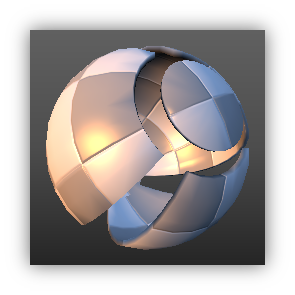
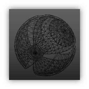
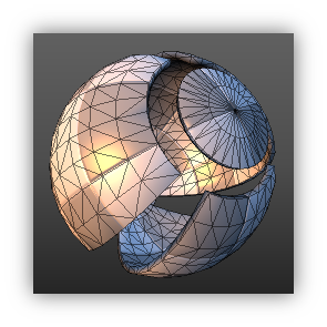
Shading: Select the type of shading you plan to use for the active render layer while editing. You can choose between Shaded, Wireframes or Shaded+Wireframes. To quickly cycle through the shading modes you can press the Tab key while a viewport is focused and in editing mode.
 |
 |
 |
|
Render: Click (or tap) on the combo box to display the list of the active render layer(s) present in your scene. Select a render layer to edit by clicking on it; or select Application to draw the final composition of all your render layers. To swap between render layer editing and your final scene composition press the Space Bar.
To quickly select a render layer while editing you can use Shift+NumX to select a specific render layer using its position in the list. In example Shift+Num1 will select the first render layer; Shift+Num2 the second and so on...
If a render layer is selected the ( ![]() ) icon (located at the top right of the options box) allows you to switch between the viewport camera and the render layer camera (if any).
) icon (located at the top right of the options box) allows you to switch between the viewport camera and the render layer camera (if any).
- Note
- If you have more than 10 render layers you can use
Ctrl+Numto select a render layer index greater than 10,Alt+Numfor greater than 20 andCtrl+Altfor greater than 30. Please take note the maximum render layer count is set to 32.
Show Grid: Toggle the grid floor on/off. In addition, you can also select which axis will be visible using the XYZ buttons.
Grid Lines: The amounts of grid lines to be displayed while being in perspective view; this value will be multiplied by the Grid Scale and will also be used when snapping objects to the grid.
Grid Scale: Change the distance between the grid lines.
Auto. Perspective: Automatically switch the camera lens to orthographic when the viewport camera is in the top, front or side view.
Toggle Quad View: Toggle the viewport single or quad view. To change which viewport will be displayed in single view simply focus it and press Q. Repeat this process to swap between which single viewport you would like to use in the quad view.
Synchronize Orthographic Views: Only available when "quad view" is enabled; this option allows you to keep all the 2d orthographic view (if any) synchronized. Panning or zooming a view will automatically have the same impact on all 2d view available.
Lock Orthographic View Rotation: This option is also only available when "quad view" is enabled; this checkbox prevent any rotational changes on all orthographic (2d) viewports (if any).
Camera
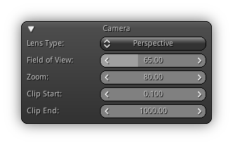
Lens Type: Modify the lens type of the active viewport camera; either perspective (3d) or orthographic+zoom (2d).
Field of View: Only available when the viewport camera mode is set to perspective; this value controls the wideness of the camera lens.
Zoom: How far the camera is from the turntable point of reference.
Clip Start: The near clipping plane distance.
Clip End: The far clipping plane distance.
Transform
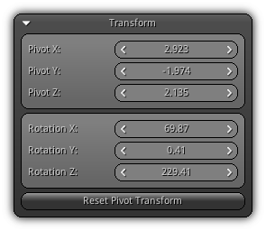
Pivot XYZ: The current position of the turntable pivot in 3d space.
Rotation XYZ: The current rotation in 3d space around the pivot
Reset View Transform: Restore the active viewport camera back to its default (home) position.
Navigation Tools
To acces the navigation tools properties page press the ![]() in the top left toolbar of the view3d.
in the top left toolbar of the view3d.
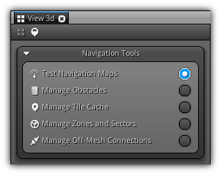
The navigations tools embedded within the View 3d gives you visual control over navigation and pathfinding. Using these tools you will be able to manage obstacles, optimize the auto-generated tile cache, control zones and sectors as well as junctions (a link between two navigational maps) and be able to create off-mesh connections (links between one point to another on the map). And finally, visualize and debug in real-time the navigation path from an arbitrary point on a map to another.
Test Tool
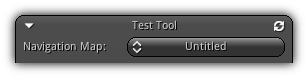
Test different navigation path using an existing map. The walkable height and radius s well as the acceptable ledge height values of the dummy character is directly taken from the settings you use when creating the selected navigation map.
Navigation Map: Select an existing navigation map to debug its pathfinding behavior using the character values previously set when building the map. To recalculate the navigation path click the ( ![]() ) icon.
) icon.
Using this tool is pretty straight forward; first, select a map, adjust the settings then drag your mouse or touch over the viewport to place the starting point. Tap or click to confirm then drag again to choose the endpoint; click to confirm of push Esc to change the previous point.
Options
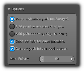
In the options section, you adjust the behavior and the range of the navigation path to be tested.
Keep navigation path unchanged: Use the default navigation points.
Add point when area changes: When the navigation path encounters a zone or a sector extra points will be added. In practice, while scripting this allows you to determine an area change and trigger something using this information.
Add a point at every edge crossing: Add extra point when the path encounter a triangle edge of the navigation map geometry.
Stich point(s) for each junction: A junction basically allows you to link one or more navigation map together (ie: when multiple scenes are loaded simultaneously or additively). This option controls the navigation path behavior when a junction is encountered. Turning this options off will stop the path at the nearest junction, turning it on will force that pathfinding algorithm to continue to try to reach the target using other navigation maps currently loaded in your application. Take note the maps walkable height and radius parameters between maps have to be the same in order to be able to extend (stitch) the pathfinding controls points.
Convert path into smooth curves: If enabled the resulting control points will be converted into a smooth Bezier curves; else the path will be linear.
Max. Points: Control the maximum amount of control points that can be used to reach the destination target.
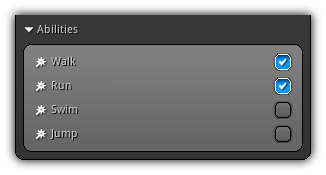
Abilities
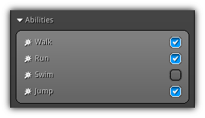
Modify the ability mask to use when testing a navigation path. When navigating basically every tile, zone and sector contains a mask that represent the type of ability that can be used to traverse it; by selecting which ability the current path query is using this allows you to control if a non-player character can or cannot pass a specific type of area that requires a certain ability.
In the screenshot above the NPC cannot swim, it can only walk, run and jump so every area marked to require the swimming ability will be avoided.
Zone Cost
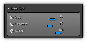
Allow you to change and tweak the value of each zone and directly see the impact on the navigation path. The pathfinding algorithm will always try to find the shortest and fastest path to go from a point A to a point B; depending on how much a specific zone costs the resulting control points can be different. When it comes to zones its simple; the lowest the cost the fastest you can travel on it, the higher the cost the slower it will take to reach your destination when traversing it.
- Warning
- Changing the cost will directly set the property of the zone. The cost slider is there only for a question of convenience avoiding you to go back and forth between the
Test ToolandZones and SectorsTool. That value you set is not to be used only within theTest Tool.
Start / End Point
Once a point is set (either or starting or ending point) you can manually tweak its XYZ location in world space by using the spinners contained in this section of the Test Tool.
Manage Obstacles
Allow you to visually manage navigation obstacles. Using this tool you can create tri-dimensional obstacles and place them directly on one or multiple navigation maps.
By selecting on which map your obstacles belongs too you can create multiple versions of your navigation maps or you can build a different version of a specific type of entity. This way you can block certain path and areas or force a certain type of entity to bypass or pass over structural features of your 3d scenes.
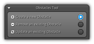
To change the editing mode of the obstacle tool simply toggle the radio buttons located at the top of the tool interface.
Create a new Obstacle: Toggle the obstacle creation tool. To place an obstacle simply hover your mouse of touch over the 3d viewport and click/tap to confirm its location.
Remove an existing Obstacle: Place your mouse or finger over the obstacle you want to delete and click/tap to confirm.
Update an existing Obstacle: First, select an obstacle by clicking or tapping it. You can then modify all properties listed in the section below.
Properties
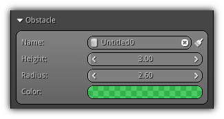
Name: A unique name to use for the new or active obstacle. To remove all existing obstacles click the ![]() . If you are in update mode you can have access to the clear icon (
. If you are in update mode you can have access to the clear icon ( ![]() ) allowing you to remove the active obstacle without having to change the tool mode to "remove".
) allowing you to remove the active obstacle without having to change the tool mode to "remove".
Height: Control the Z dimension of the obstacle.
Radius: Control the size of the X and Y axis of the obstacle.
Color: Allows you to assign a specific color to obstacles so you can create your own color scheme using the active obstacle type.
Map Mask
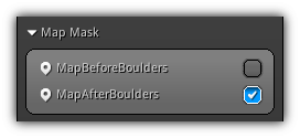
For each obstacle, you need to choose which navigation map will be affected. To do that you simply have to select and toggle the checkbox of the map(s) at creation time or during an update.
Pivot
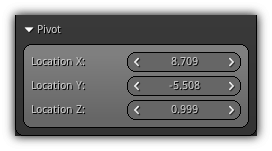
Preview the active XYZ location in world space in creation mode; while in update mode the controls become active and you can manually either tweak the existing location or specify a new one for the active obstacle.
Manage Tile Cache
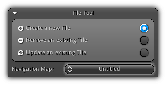
Even when planning carefully the approximated geometry to use for your navigation maps you will realize that in some cases some areas are still going to be inaccessible. To optimize your maps to only calculate navigation paths to a location that is unreachable you can use the Tile Tool to remove some tiles that cannot be reached by any possible navigation path.
Create a new Tile: Move your mouse or touch over the area that does not have a tile but is inside the boundary of the selected navigation map; tap/click to confirm.
Remove an existing Tile: Move your mouse or finger over an existing tile; once highlighted click/tap to proceed with the removal of the tile.
Update an existing Tile: After updating the navigation mesh you do not need to rebuild the whole map. Simply select the tile that you wish to update by hovering your pointing device on top of it, then push it to update.
Navigation Map: Select an existing navigation map to manage its associated tile cache.
Tile
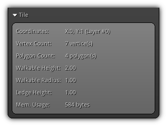
Give various information about the current tile currently active.
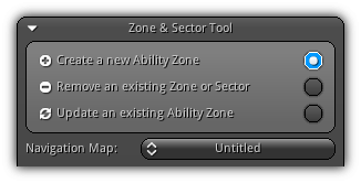
Manage Zones & Sectors
The Zone & Sector Tools help you to create areas an existing map that requires one or more ability to traverse. The first area that uses a certain combination of abilities will create a Zone that contains a Sector.
Optionally all subsequent areas created using the same abilities will create a new Sector and will automatically be attached to the initial Zone (please refer to Construction for more information).
This approach is optional but recommended; so at runtime, while scripting something, whatever condition happens in your app. all sectors contained within a zone can change the type of abilities required to traverse it (ie: The player gets the iron boots, and can now walk on fire).
The zone tools also allow you to change the course of navigation paths assuming that NPC are different sizes; (ie) A giant cyclops is not affected much by stepping into a swamp but a regular human will drastically be slowed down by it.
The operations of this tool are similar to the other navigation tools to manage your zone and sectors first choose an editing mode and select a navigation map; set the tools options and parameters and click/tap to confirm within the 3d viewport.
Create a new Ability Zone: Set the ability zone tool to creation mode.
Remove an existing Zone or Sector: Give you the opportunity to remove one or all zones and sectors of a specific type. To remove a zone/sector place your mouse on top of it in the appropriate viewport that displays the selected navigation map the click to confirm the remove operation.
Update an existing Ability Zone: Over your mouse/touch over the appropriate zone or sector to select it. Once selected simply change its parameters; no need for confirmation, changes are done automatically in real-time.
Navigation Map: Select an existing navigation map to operate.
Zone
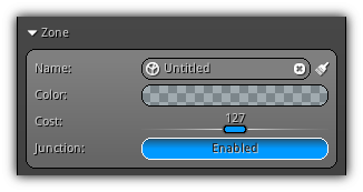
Name: This field can be used to set the name for a newly created zone and sector. In update mode used to change the active selection name. To remove all existing zones and sectors click the ![]() icon. Also, available in update mode the clear icon (
icon. Also, available in update mode the clear icon ( ![]() ) allow you to remove corresponding zones/sectors that share the active abilities as the selection without having to change the tool editing mode.
) allow you to remove corresponding zones/sectors that share the active abilities as the selection without having to change the tool editing mode.
Color: Set/Update the color to use for a new/existing zone and its subsequent sector(s).
Cost: When querying a navigation path this value will be used to determine how much would it cost if the path has to traverse this type of areas. As a rule of thumb: the lower the faster; the higher the slower.
Junction: Specify if the current zone or sector might be connected to other external navigation maps available in the same scene or another loaded scene. When querying a path if a zone/sector is tagged as junction it will force the algorithm to check there is another navigation map overlapping and if the traversal should be extended or should stop.
Abilities
Select/Update the type of ability is required in other to traverse the zone and the sectors attached to it.
Construction
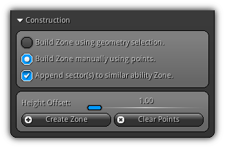
The construction options are only available during creating mode.
Build Zone using geometry selection.: Uses the current mesh selection within the desired viewport to create a new zone or sector.
Build Zone manually using points.: Allows you to specify manually each point to create a new zone or sector. To operate this construction mode simply hover your mouse or touche and click/tap to create a new point.
Append sector(s) to similar ability Zone: When a new area is created force the system to lookup for existing areas that have the same ability selection as the newly created one. If turned off, a new zone will be created ignoring any similar existing ones.
Height Offset: Increase the height of the zone or sector. This is useful when the terrain is not equal; like that you can ensure that all triangles that are included within your selection will be affected by the new zone or sector.
Create Zone: When at least three points have been specified (in manual mode) or at least one valid geometry selection is available this action will be available. Activate it when you are satisfied with your creation (please take note points or geometry selection cannot be modified in update mode, you will have to remove and create a new one).
Clear Points: Only available in manual creation mode this action allows you to remove all existing control points and start fresh.
Manage Off-Mesh Connections
Off-Mesh connections basically allow you to connect one part of a navigation map to another using an existing ability set. It can be used to determine: (ie) if an entity can jump down a to a lower level or have to use the road to get down there or (as another example) if the NPC can climb up a certain cliff to get to its destination etc...
Connections can be either be directional or bidirectional and require (similar as zones and sectors) a specific set of abilities to be eligible during pathfinding.
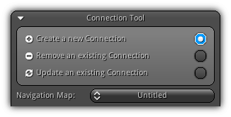
The operation of this tool is no different from the previous tools that you have been studying so far. First, select the mode, then the map and use your pointing device over a viewport to place the start (confirm with click/tap) and end point of the connection. To get back to modify the previous point simply press Esc.
Create a new Connection: Set Off-Mesh Connections tool to create a new connection.
Remove an existing Connection: Select a connection with your pointing device; clip/tap to confirm.
Update an existing Connection: Over your mouse/touch over the connection you want to update and select it. Once it is selected, you can then update/tweak its parameters.
Navigation Map: Select an existing navigation map to create/update/remove connections.
Connection
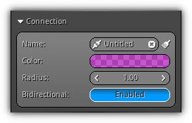
Name: A unique name to use for the connection; in update mode used to change the active selection name. To remove all existing connections simply click/tap the ![]() icon. While updating a connection use the clear icon (
icon. While updating a connection use the clear icon ( ![]() ) to remove the active connection without having to switch the tool for removal.
) to remove the active connection without having to switch the tool for removal.
Color: A color to visually identify a new or existing connection.
Radius: Represent an invisible sphere that covers the map area where the connection can be taken into consideration while calculating a navigation path.
Bidirectional: Determine whether or not the connection can be used in both direction; if not, only the direction from the starting point to the endpoint will be used.
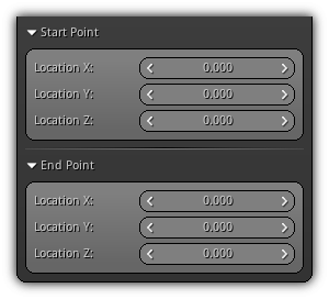
Start Point / End Point
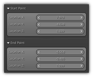
Display the current start and end point of a new or active connection (update mode). While updating the controls are available to you to tweak or adjust the current location of both points.
Abilities
Control the ability mask for the new or active selection. Using theses abilities the navigation path query will use this information to adjust the path control points according to this mask.
Paint Tools
The paint tools settings and properties page are available by toggling the ![]() button available from view3d the top left toolbar.
button available from view3d the top left toolbar.
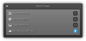
The built-in Paint Tools allows you to create custom brushes to scatter objects; paint vertex color, paint directly on an existing texture and provides vertex sculpting functionalities. All tools, visual feedback and controls are directly accessible from within any view3d available on your workspace layouts.
Scatter Brush
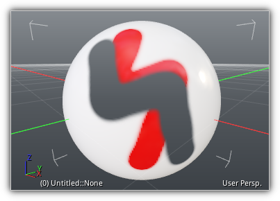
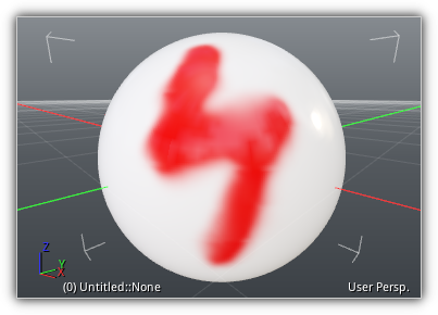
Vertex Paint
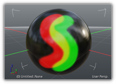
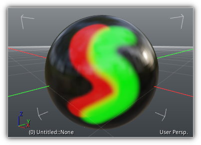
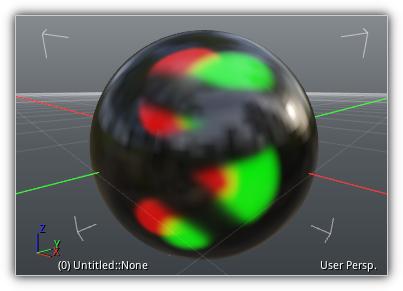
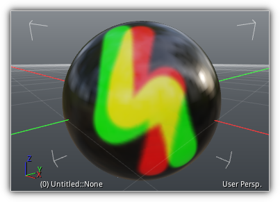
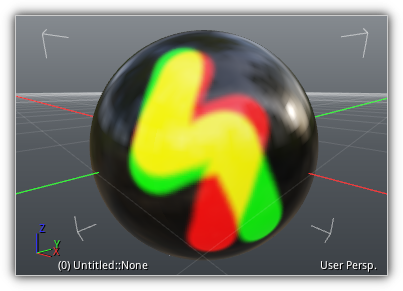
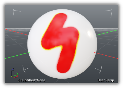
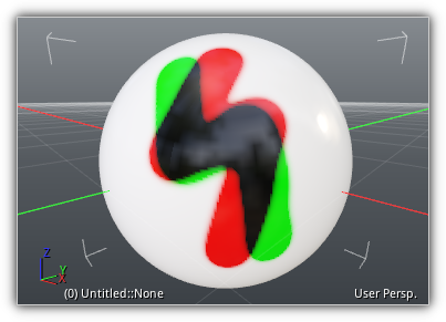
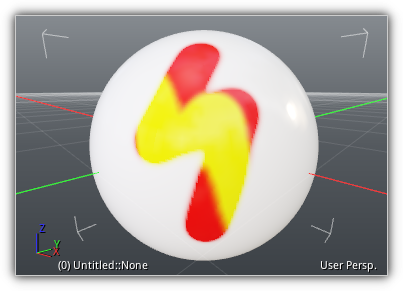
The color tool allows you to directly paint using vertex color on existing geometry. The resulting vertex color can then be used inside your shaders to colorize, blend, fake lighting or ambient occlusion, and more. Vertex color painting can be applied on static mesh and if LODs already exist they will have to be regenerated when the painting session is over.
Mode: Select the brush blending mode; choose between one of the 20+ modes available. In addition, you can cycle through the different modes by pressing [ (previous) and ] (next).
 |
 |
 |
 |
 |
 |
 |
 |
 |
 |
 |
 |
 |
 |
 |
 |
 |
 |
 |
 |
 |
|||
Color: Set the primary and alternate color using the Color Picker; while painting to access the alternate color hold the Ctrl key.
Radius: The size of the paintbrush. You can also press Ctrl+RMB while dragging the X-axis on the left and the right while an active viewport is selected to modify it conveniently while painting.
Strength: Control the amount of impact the color and alternate color will produce. Similar to the radius, the strength can also be modified while a viewport is selected by dragging the Y-axis up and down while pressing the Shift+RMB.
Version: Connected to Ctrl+Z (undo) and Ctrl+Y (redo) this slider allows you to select a specific version of the mesh during your vertex painting session. To stop gathering versions while painting enable the ![]() . If you want to free the active versions from memory press the
. If you want to free the active versions from memory press the ![]() button.
button.
- Note
- To increase (or decrease) the number of versions available access the history depth accessible from the preferences dialog:
File > Show Preferences > Settings > History Depth.
Controls
| Key | Action |
|---|---|
| Mouse/Touche Hover | Place the 3d marker at a specific location on the geometry to select a set of vertices to operate on. |
| Left Mouse Button | Paint on the active geometry using the current blend mode using the primary or secondary color. |
| Shift + Left Mouse Button | Erase any previous vertex paint applied on the geometry. This action is similar as selecting the Erase mode and will restore back the vertex color to the one initially used when the vertex paint session was initialized. |
| Ctrl + Right Mouse Button | Increase/Decrease the radius of the brush using the X-axis. |
| Shift + Right Mouse Button | Increase/Decrease the strength of the brush using the Y-axis. |
Color Layers
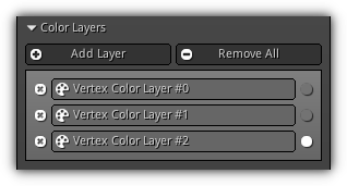
This panel allows you to add, remove and manage which vertex color layer you wish to paint on. By default, up to four vertex color layers are available on a per-mesh basis.
Add Layer: Add a new vertex color layer to the active mesh. Take note that when a new vertex color layer is created it set automatically all color to zero. To remove an existing layer press the ![]() ; to change the active vertex color layer to paint on press the
; to change the active vertex color layer to paint on press the ![]() icon.
icon.
Remove All: Remove all existing vertex color layer(s).
Brush
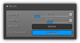
This section contains the settings that will affect the behavior of the color paintbrush.
Spacing: Determine the rate of the stroke; how much percentage of the radius should be considered to produce a new color.
Stabilize: A value of one will produce no delay between the cursor or touche and the marker; a value near zero will act as a lazy mouse effect allowing you to produce a smooth and consistent stroke.
Method: Select between Vertex mode that will snap the marker to the nearest vertex on the geometry or Triangle that will interpolate vertex coordinates and pick an accurate position on the geometry. To accelerate painting on large geometry a third method is available (Accelerated) which requires to have reduction data available for the active geometry; refer to the Library Geometry section for more information. Once the reduction data is generate you can select this method and use the acceleration structure to increase the vertex painting performances.
Color Squared: Use the square value of the color; which generally looks better than using raw RGB values. Take note that no colors are gamma-corrected and should be handled manually in the shader or by another user-based process.
Falloff
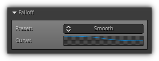
In this area, you set up the falloff of the brush; use one of the available presets or select Custom to create using the Curve Picker your normalized curve.
Preset: Assign one of the available presets to the brush falloff curve.
Curve: Preview of the active falloff curve; when the preset is set to Custom you can press it to open up the Curve Picker.
Colors
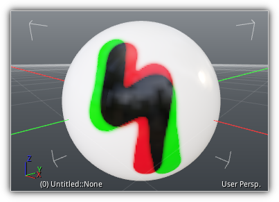
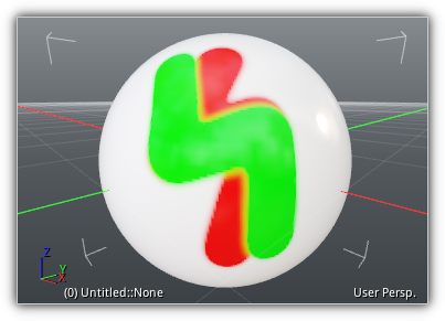
The Colors section gives you access to generic utility functions to either generate vertex color or use on the existing vertex color layers. When an operation involves a color; the primary color is used by default; however you can still use the secondary color by holding Ctrl before processing.
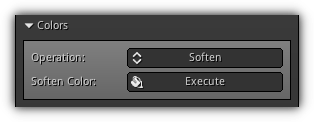
Operation: Select the type of operation to effectuate the active vertex color layer.
| Operation | Preview | UI |
|---|---|---|
| Fill | 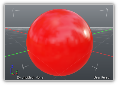
| 
Ctrl to alternate). |
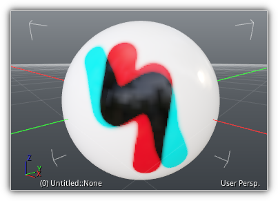
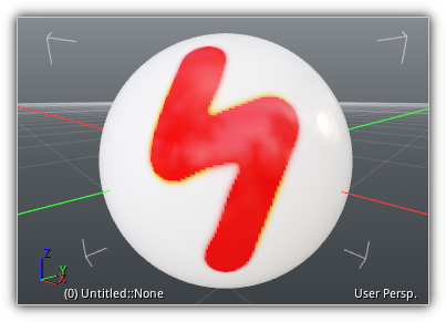
| Invert | 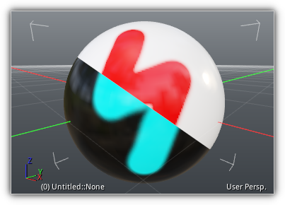
| 
|
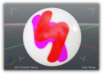
| Soften | 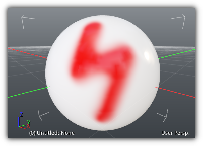
| 
|
| Levels | 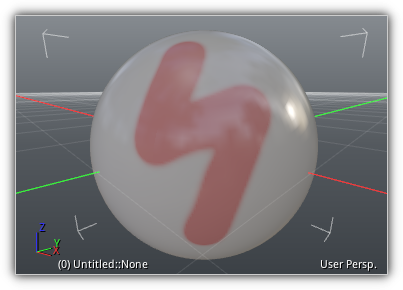
| 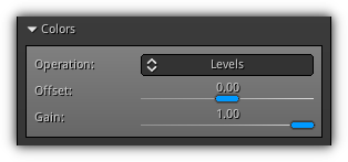
Offset: The offset amount to add to the active RGB values. Gain: Multiplier used to calculate the amount of the offset RGB value of the active color layer. |
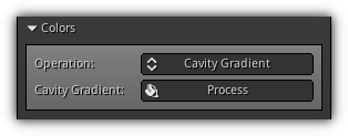
| Cavity Gradient | 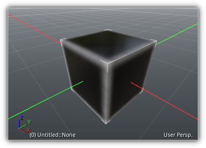
| 
|
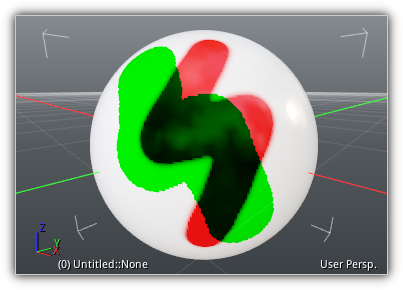
| Brightness, Contrast | 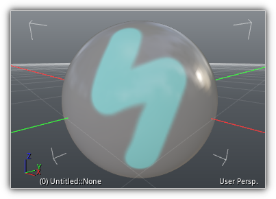
| 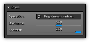
Brightness: The amount of brightness to apply to the active vertex colors. Contrast: The amount of contrast to apply to the vertex colors. |
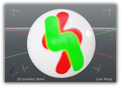
| Hue, Saturation, Lum. | 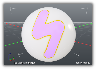
| 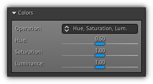
Hue: The amount of hue to apply to the vertex colors. Saturation: Control the saturation of the active vertex colors. Luminance: Specify the amount of luminance that should be applied on the RGB values. |
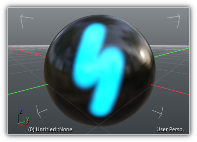
Visualization
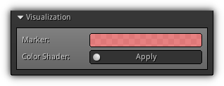
Dedicated section to make visualization while painting easier. The marker field allows you to use the Color Picker to change the color and alpha value of the vertex set picked on the geometry. The color shader entry either generates or applies a vertex color shader that is connected to the active vertex color layer selected for editing.
Marker: Open up the Color Picker allowing you to select a different RGBA value for the vertex painting marker.
Color Shader: Generate or apply a predefined shader to visualize the active vertex color layer used by the painting tools.
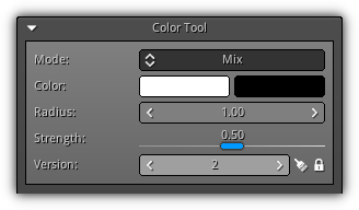
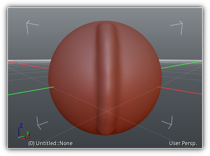
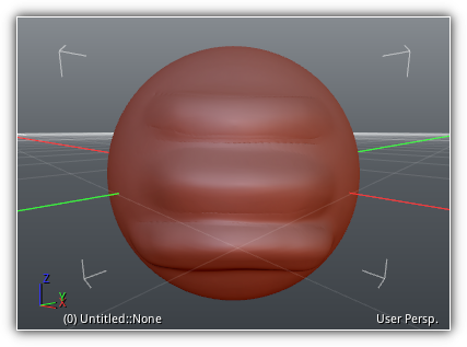
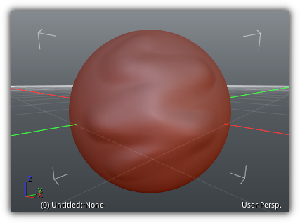
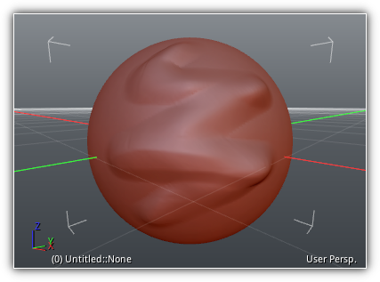
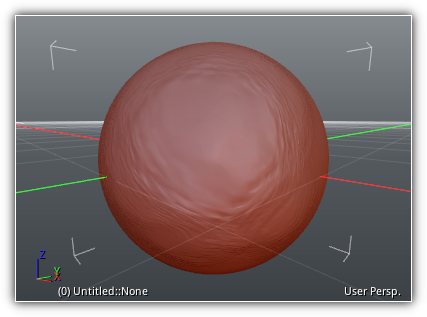
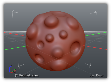
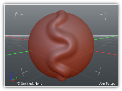
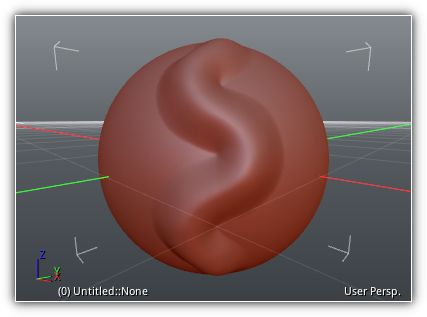
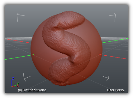
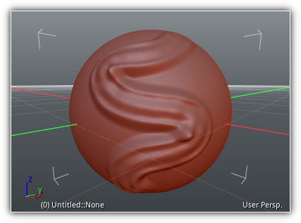
Vertex Sculpting
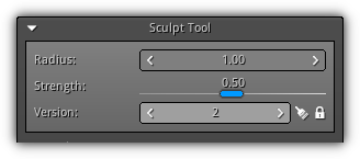
This tool provides vertex sculpting functionalities; it is in no way supposed to replace dedicated sculpting software such as Zbrush or the sculpting functionalities of (ie.) Blender. These tools are available to allow you to do modifications and adjustments on a vertex level to existing geometry already imported in your current project.
Take note that sculpting can only be applied on static meshes, or at the base level of other types of meshes. If the mesh contains multiple levels of details; these LOD will have to be regenerated after the sculpting session is over.
Radius: Control the size of the active brush. It can be adjusted directly or from any viewport by holding Ctrl+RMB and by dragging the mouse on the X-axis.
Strength: The hardness factor of the active brush control the impact of the brush on the active point set. From a viewport hold Shift+RMB and drag on the Y-axis.
Version: This control provides a convenient way to select a specific version of the sculpted geometry. It acts as a local undo/redo mechanism that can be accessed by the shortcut Ctrl+Z and Ctrl+Y. To accumulation versions while sculpting toggle the ![]() . If you want to release the memory used by the current versions accumulated press the
. If you want to release the memory used by the current versions accumulated press the ![]() button.
button.
- Note
- The version number is controlled by the
history_depthparameters of the general settings. To change this value to a higher (or lower) number you can do so by accessing the following setting:File > Show Preferences > Settings > History Depth.
Controls
| Key | Action |
|---|---|
| Mouse/Touche Hover | Place the 3d marker at a specific location on the geometry to select a set of points to operate. |
| Left Mouse Button | Draw on the geometry using the active brush. |
| Shift + Left Mouse Button | Erase any previous stroke applied on the geometry restoring back the vertices to their original position (same as selecting the Erase brush manually). |
| Ctrl + Right Mouse Button | Increase/Decrease the radius of the brush using the X-axis. |
| Shift + Right Mouse Button | Increase/Decrease the strength of the brush using the Y-axis. |
Brush
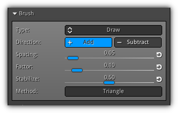
Control the settings of the current brush. There are three types of brushes: draw brushes (such as draw, inflate, etc...), strength brushes (such as erase, smooth, or flatten), and move brushes (grab, smear, deform). Based on the type of brush selected some settings might be unavailable as they only apply to a specific type.
Type: Select which brush algorithm to use. Refer to the table below to learn more about each brush type and their effect on the active point set. You can also cycle the brush type by pressing [ and ].
 |
 |
 |
 |
 |
 |
 |
 |
 |
 |
||
Direction: Determine if the stroke will push inward or outward the vertices.
Spacing: The distance between each stroke is based on the radius amount.
Factor: Brush multiplier that specifies the amount of impact the brush will have on the active point set.
Stabilize: Threshold that determines the amount of delay between the mouse or touche and the sculpt marker.
Method: Determine how the active point (and its subsequent point set) will be picked; choose between triangle (interpolation) or vertex (nearest point in proximity).
- Remarks
- To restore a specific settings to its default value press the
 button located on the right side of the control.
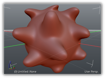
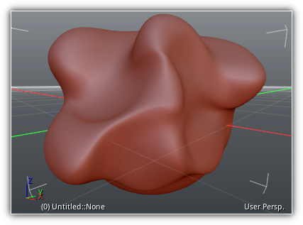
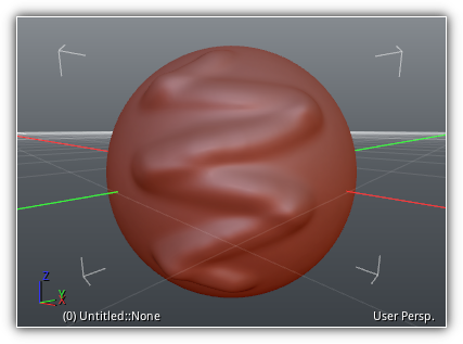
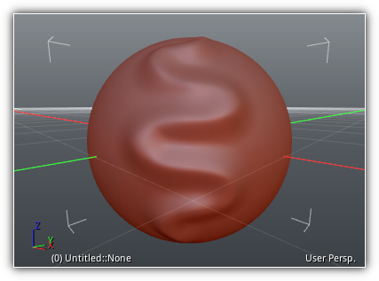
Shape
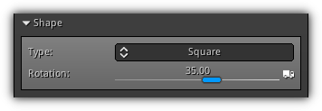
Available to all types of brush this section allows you to modify the shape of the stroke used by the 3d marker. Select between Circle (default), Square (to simulate clay strips), Stripe (for rectangular clay layer), and Diamond (triangle shape initiated from the center of the marker).
Type: The type of shape to use for the active brush stroke. To quickly change cycle through the brush shape you can press { to jump to the next one and } to the activate the previous.
 |
 |
 |
 |
Rotation: The base rotational angle to apply to the shape. You can additionally take into consideration the angular direction of the stroke by pressing the ![]() .
.
- Note
- Rotational and angular settings do not apply to the shape type
Circle.
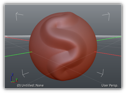
Falloff
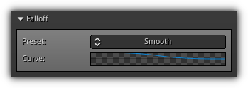
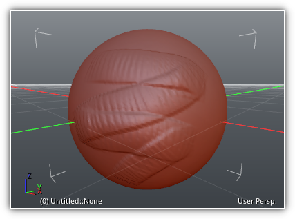
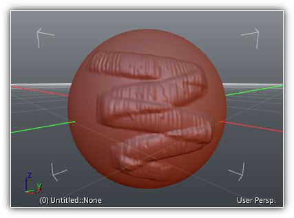
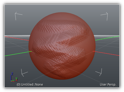
Common to all brushes a falloff can be used to control how much the vertices of the active point set will be affected by the stroke. You can select between the following presets: Smooth, Sphere, Sharp, Linear, Constant. To create your own you can simply select Custom and use the Curve Picker to specify to create a normalized curve.
 |
 |
 |
 |
 |
 |
||
Visualization
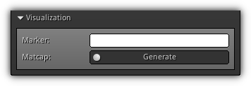
Color: Customize the color of the sculpt marker using the Color Picker.
Matcap: Automatically generate (or apply if it already exists) a standard clay matcap to the active selected object.
- Remarks
- The Matcap material, shader, and texture will be placed by default at the root of your project.
|
|