
This tab of the properties is dedicated to physics. By setting the various properties found within this tab you can prepare your object for physics simulation. Once an object or bone is selected the associated physics properties can be found within this tab. To add physics to an existing object or bone start by activating it using selection and follow the instructions found within this help page.
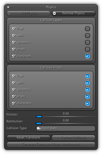
Add Physics: Select the type of physics you want to apply to the object; choose between Static, Rigid Body or Soft Body (Dynamic Mesh only).
Remove Physics: Remove all the physics behaviors of the active object.
Collision Layers: Select on which collision layer the physic object will be placed on.
Collision Filters: Select which collision layer the physic object can collide with.
Friction: Base friction of the physic object.
Restitution: Base restitution of the physic object.
Collision Type: For reference only; the active physic collision type is displayed for the active object.
Reset Transform: Reset back the physic object to its initial position before the simulation.
Restore SoftBody: Restore back the soft body to its original topology before being deformed by the physic simulation.
Generate Compound from Attachments.: Apply only for a static or rigid body physics; this option allows you to generate a compound shape depending on the collider information of the active object attachments. Consequently, physics settings applied to the attachments will generate local colliders that will be used as a compound shape.
Events
Once an object has physics enabled, new callbacks are available to report the collision at various stages between physic objects. Theses new callbacks can then be triggered and dispatched for all scripts connected to the object which respond to them.
| Callback | Description |
|---|---|
OnOverlap() | Occur when two physic object axis aligned bounding boxes are overlapping. This does not mean that a collision occurs yet; only report that two physic objects are in proximity. |
OnCollide() | This callback is triggered when two physics object are in proximity and can collide (depending their collision masks and filters). |
OnContact() | Triggered when two physic objects are actually colliding. This callback occurs during the material combiner (which evaluates friction, restitution) phase which indicates that contact points have been created and a collision is occuring. |
Colliders
Available when the collision type is either Static or Rigid Body the colliders properties allow you to manage and manipulate the physic bounds that will construct the shape of the physic object that will be used during simulation.
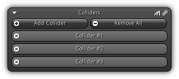
Add Collider: Select from the shape list the type of collider you wish to create. Refer to the table below to learn more about each collider type.
Remove All: Delete all existing collider(s).
| Type | Description |
|---|---|
| Box | A cube shape that extend on XY and Z axis. |
| Sphere | A ball shape collider using a uniform radius. |
| Cylinder | A cylinder shaped collider where the height and the radius can be specified. |
| Capsule | A cylinder which uses two hemispheres at its extremity; height and radius can be specified. It is ideal the ideal shape for characters. |
| Cone | A cone shape collider created using the base radius and the height specified. |
| TriangleMesh | This type of collider is created using an existing geometry. Take note the density of the triangles will affect the performance; try to keep the triangle count at its minimum; or use ConvexHull. |
| ConvexHull | This type is also built from geometry but contrarily as the TriangleMesh this type of collider will use the vertex information of the geometry. Optional optimization is also available to reduce the amount of points used by the collision shape. Hence, it is generally giving better performance than a triangle mesh collider at the cost of shape accuracy. |
It is recommended (but not necessary) to use only one specific collider per physic object. Each basic collider shape has specific optimization that will allow them to perform better.
When more than one collider is created, the system will create a compound shape using all colliders' information. Compound shapes performances are lower than basic shapes, but gives more flexibility (but are still in many cases faster than TriangleMesh and ConvexHull).
![]() .
.
However, if you need to force a single collider to be treated as a compound shape press the ![]() . Therefore, you can then specify a transformation offset to use for the single collider (which is not available for basic shapes).
. Therefore, you can then specify a transformation offset to use for the single collider (which is not available for basic shapes).
Once a collider is created, it will be appended to the colliders list. To remove a specific entry press the ![]() button located on the top left side of the entry box.
button located on the top left side of the entry box.
Collider Settings
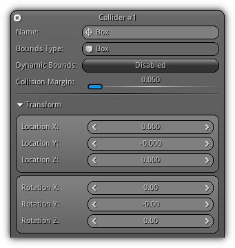
Name: A unique name to identify the collider.
Bounds Type: The basic shape type the collider (read-only).
Dynamic Bounds: Force the system update the collider dimension using the active scale the object.
Collision Margin: Value used to avoid penetration issues during simulation; tweaking this value will create an invisible margin around the collider preventing physic objects to pass between each other.
Transform: Available only when the physic object is a compound shape; this allows you to set a local transformation offset for each collider.
Physic Material
For each collider a physic material can be specified; the physic material will set the friction and restitution of the collision and dictate how these two values should be combined. In the case of Soft Body physics, the linear stiffness will determine the elasticity of the nodes affected by the collision. If no physic material is provided that the system will automatically use the default values specified by the physic engine (friction = 0.5, restitution = 0, linear stiffness = 1.0 and multiply mode for combiners).
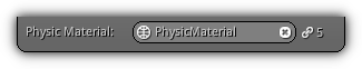
Physic Material: Manually enter the name of an existing physic material or press the ![]() to display a complete list of all available assets. Clear the active physic material by entering an empty name or press the
to display a complete list of all available assets. Clear the active physic material by entering an empty name or press the ![]() button. The
button. The ![]() display the amount of resources currently connected to the specified asset.
display the amount of resources currently connected to the specified asset.
Box Settings
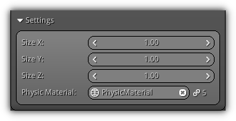
Size XYZ: The size of the box on each axis.
Sphere Settings
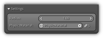
Radius: The radius of the sphere collider.
Cylinder, Capsule, Cone Settings
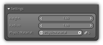
Radius: The base radius of the collision shape (XY axis).
Height: The height of the shape on the Z axis.
Triangle Mesh
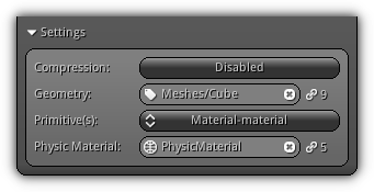
Compression: Determine whether quantized AABB compression should be used when creating the collision mesh. Only available if the physic type is Static and does not apply in the case of dynamic or rigid body physics.
Geometry: The geometry data to use to create the triangle mesh. Press the ![]() icon to open the list of all available geometry; click an entry to select. Push the
icon to open the list of all available geometry; click an entry to select. Push the ![]() icon to cancel the selection.
icon to cancel the selection.
Primitive(s): For each existing primitive you can specify a different physic material. It is ideal to seamlessly define different friction area including ie. mud, grass, sold, ice etc... Click the combo box to display the list of all available primitives for the selected geometry; select an entry then specify the Physic Material to use.
Convex Hull
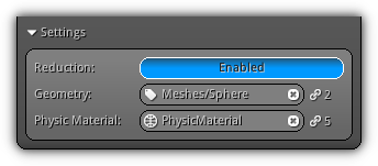
Reduction: Only use the outermost points that define the shape. Take note for best performance it is recommended that your convex hulls contain less than 128 points for maximum performance.
Geometry: The geometry data to used to create the convex hull. Press the ![]() icon to open the list of all available geometry; click an entry to select. Push the
icon to open the list of all available geometry; click an entry to select. Push the ![]() icon to cancel the selection.
icon to cancel the selection.
Rigid Body Settings
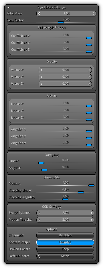
Total Mass: The weight of the object in kilograms. If the value is 0, the object is considered a static object.
Form Factor: The form factor of the inertia tensor.
Anisotropic Friction
Coefficient XYZ: Control the internal friction damping by altering the value for each axis; like this, you can control the impact of friction on a per axis basis (this vector is always relative to the friction direction vector).
Gravity
Vector XYZ: Allow you to specify a custom gravity vector to use for a specific rigid body. A vector value of 0,0,0 tells the system to use the standard gravity vector set up in the World properties.
Factors
Linear XYZ: Linear factors allow you to specify the influence of the object movement on each axis.
Angular XYZ: Angular factors works the same way as is linear counterpart at the exception that it is applied to the rotation of the object.
Damping
Damping can improve the stability of low pass jitter.
Linear: Control the linear damping of the rigid body.
Angular: Control the angular damping of the rigid body.
Thresholds
Contact: Specify for how long a contact point is still considered alive before being destroyed (1.0 = 1 sec.).
Sleeping Linear: The linear sleeping threshold value in seconds; where 1.0 = 1 sec. If the rigid body linear velocity is stable for that period, the physics object will be deactivated.
Sleeping Angular: Same as for linear but control the angular sleeping threshold value.
CCD Settings
Available only if the World collision detection mode is set to Continuous. These parameters allow you to control the size of the swept sphere and motion threshold that will be used by the continuous collision detection system.
Swept Sphere: The sphere radius to used to calculate continuous collision detection between two frame time.
Motion Thresh.: The motion threshold that will be used as interpolation factor between the current and the previous frame.
Options
Kinematic: Specify if the rigid body transformation should be updated directly by the physic engine or it will be specified by the user. This option is crucial when creating a character controller or rag dolls. Kinematic objects are objects without a mass but the user can move them. There is only a one-way interaction with them and the physic engine will calculate the velocity of the object using the time step of the previous and current world transformation.
Contact Resp.: Control whether the object should have a contact response. This option can be used to temporarily disable all contacts with any other physic objects while still detecting collision; in other words to create a ghost object.
Broken Const.: Determine the method to use when a constraint breaks. Select between Keep which will maintain the constraint alive (in case it needs to be re-used) or Destroy which will immediately remove the constraints.
Default State: Specify the default state of the physic object when the application starts. Choose between Active, Deactivated which will put the physic object on standby, Disable Deactivation forcing the physic object to stay alive or Disable Simulation which will cause the physic object to be excluded from the physic simulation.
Rigid Body Constraints
Constraint allows you to limit the linear and/or angular movement of a rigid body in space. A rigid constraint can either be specified in world space or in relation to another physic object. Various constraints are available to simulate a multitude of scenarios ie. hinge of a door, a zip line, a punching bag, rag dolls, vehicle and a lot more.
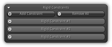
Add Constraint: Press the button to populate the list of all available constraint type. Select one to create it; refer to the Constraints Types table below to learn more about each them. Once added the constraint will appear on the list (as shown in the image above). To remove an existing constraint press the ![]() button.
button.
Remove All: Clear up the list and remove all constraints attached to the active rigid body.
Constraints Types
| Type | Description |
|---|---|
| Ball | Create a point to point constraint. If no other rigid body is specified, the system will create a ball constraint ideal to simulate objects that are hanged on ceiling etc... 
|
| Fixed | Creates an attachment; similar as a pin either in world space (if no other rigid body is specified) or relative to another existing rigid body. The preview below display the constraint being turn on and off; to display the pin attraction behaviors. 
|
| Hinge | Create a movable joint mechanism like the one found on doors and gates. 
|
| Twist | Create cone twist constraint. 
|
| Slider | Create linear constraint that allow the physic object to slide from one point to another; worth mentioning that angular limits can also be set. 
|
| Generic | Basically an all-in-one constraint; the various parameters and settings that can be adjusted; this type of constraint can basically simulate all others (and more due to its flexibility). It is more computationally demanding than the other which are more optimized to achieve only a specific task. 
|
Settings
The properties enumerated below are common for all constraints and represent the base settings of a constraint.
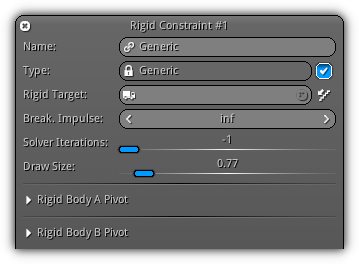
Name: A unique name that represents the constraint within the physic object it is associated with.
Type: The active constraint type (for reference only). The checkbox ( ![]() ) located on the right side of the control allow enable or disable the constraint.
) located on the right side of the control allow enable or disable the constraint.
Rigid Target: Select another rigid body the active constraint should be interacting with. Press the ![]() to populate the list of all valid physic object the constraint can be connected to; select an entry to connect it. Press the
to populate the list of all valid physic object the constraint can be connected to; select an entry to connect it. Press the ![]() to disconnect; to enable or disable collision between the two rigid bodies (the active one and the one connected) press the
to disconnect; to enable or disable collision between the two rigid bodies (the active one and the one connected) press the ![]() button.
button.
Break. Impulse: The amount of force that can be applied on the constraint before it breaks.
Solder Iterations: Manually set the number of iterations the constraint solver should effectuate while resolving the active constraint. A value of < 0 force the system to use the default value assigned for this type of constraint (recommended).
Draw Size: Change the size of the constraint visualization. This value is used for debugging purposes only and will only be visible while the View3d is in edit mode.
Rigid Body A Pivot: Specify the location and rotation (only if the constraint is not a Ball or Fixed type) of the constraint using the rigid body local space.
Rigid Body B Pivot: If no Rigid Target is connected; the location XYZ specified by the user is assumed to be in world space; if the location is 0,0,0 the system will interpret the rotation to be relative to the location set in Rigid Body A Pivot.
Ball
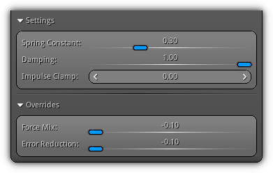
Settings
Spring Constant: Specify in term of percentage (where 1.0 = 100%) the amount of elasticity that should be applied between the rigid body and the constraint pivot.
Damping: Stabilize the amount of jittering.
Impulse Clamp: Clamp the amount of impulse that can be applied to the constraint.
Overrides
Force Mix: The constant force mix factor.
Error Reduction: Tweak the error reduction parameter used by the constraint solver when operating the active constraint.
- Remarks
- A value of < 0 tell the system to use the default value predefined by the physic engine (recommended).
Hinge
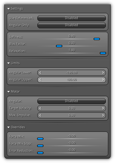
Settings
Use ReferenceA: Invert the hinge direction.
Angular Only: If not enabled the solver will only process the linear axes.
Softness: Describes the percentage of limits where the movement is free, beyond this percentage, the limit is gradually reinforced until the hard limit (1.0) is reached.
Bias Factor: Strength with which the constraint resists zeroth order (angular, not angular velocity) limit violation.
Relaxation: The lower the value the less the constraint will fight velocities which violate angular limits.
Limits
Angular Lower: The lower angle limit of the hinge.
Angular Upper: The upper angle limit of the hinge.
Motor
Angular: Enable or disable a constant motor force on the hinge.
Target Velocity: Specify the targeted amount of velocity the motor should reach.
Max. Impulse: Determine the impulse apply on the hinge.
Overrides
Force Mix: The constant force mix factor.
Force Mix Stop: The force mix factor to use when upper and lower limits are reached.
Error Reduction: Control the error reduction parameter to use by the constraint solver when solving the active constraint.
Twist
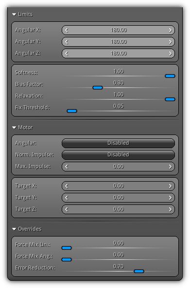
Limits
Angular XYZ: Control the rotational limit on each axis.
Softness: Describes the percentage of limits where the movement is free, beyond this percentage, the limit is gradually reinforced until the hard limit (1.0) is reached.
Bias Factor: Strength with which the constraint resists zeroth order (angular, not angular velocity) limit violation.
Relaxation: The lower the value the less the constraint will fight velocities which violate angular limits.
Fix Threshold: The threshold to used to force solving the swing limit of the constraint.
Motor
Angular: Enable angular motor force.
Norm. Impulse: Normalize the motor strength.
Max. Impulse: The impulse factor that will be accumulated by the motor.
Target XYZ: The motor target rotation on each axis.
Overrides
Force Mix Lin.: The linear constant force mixing factor.
Force Mix Ang.: The angular constant force mixing factor.
Error Reduction: Control the error reduction parameter to use by the constraint solver when solving the active constraint.
Slider
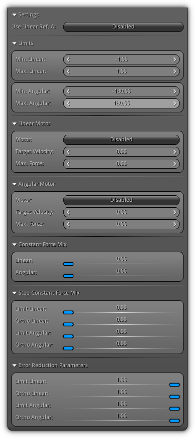
Settings
Use Linear Ref. A: Use the transformation of the active rigid body as reference frame instead of the rigid body B transformation (default).
Limits
Min. Max. Linear: Set the minimum and maximum linear limit which will be used as the "line" of the slider.
Min. Max. Angular: Set the rotational limit of the slider around the zip line created by the linear limits.
Linear Motor
Motor: Enable or disable linear motor force.
Target Velocity: The linear velocity goal the motor is trying to reach.
Max. Force: The constant force applied linearly on the constraint.
Angular Motor
Motor: Enable or disable angular motor force.
Target Velocity: The angular velocity goal the motor is trying to reach.
Max. Force: The rotational force applied on the constraint.
Constant Force Mix
Linear: Factor to use when moving inside linear limits.
Angular: Factor to use when moving inside angular limits.
Stop Constant Force Mix
Limit Linear: Factor to use when hitting the linear limits.
Ortho Linear: Factor to use when the constraint is against linear constraint axis.
Limit Angular: Factor to use when hitting the angular limits.
Ortho Angular: Factor to use when the constraint is against angular constraint axis.
Error Reduction Parameters
Limit Linear: Parameter to use when moving inside the linear limits.
Ortho Linear: Parameter to use when the constraint is against linear constraint axis.
Limit Angular: Parameter to use when moving inside the angular limits.
Ortho Angular: Parameter to use when the constraint is against angular constraint axis.
Generic
Generic constraints offer the most flexibility and contain significant different options. Learn in the next following sections the definitions of all the settings available and how the values exposed will have an impact on the functionalities of the constraint.
Limits
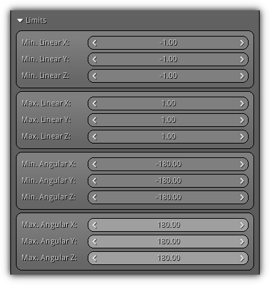
Min. Linear XYZ: The minimum limit of the box that defines the constraint linear movements.
Max. Linear XYZ: The maximum limit of the box that defines the constraint linear movements.
Min. Angular XYZ: The lower angular limits of the constraint for each axis.
Max. Angular XYZ: The upper angular limits of the constraint for each axis.
Linear Motor
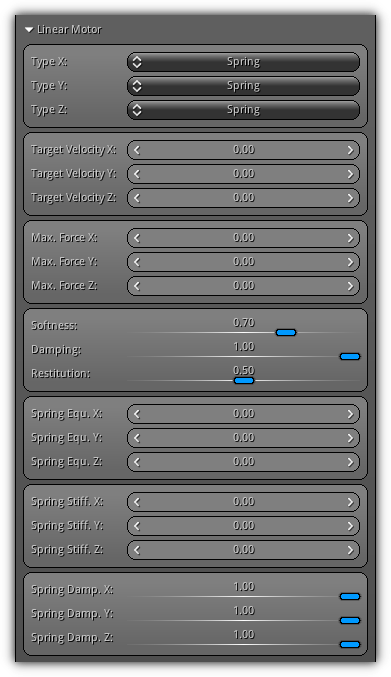
Type XYZ: Specify the type of linear motor to use for each axis; select between None (which disable motor for the axis). The type Motor will tell the system that axis will use a traditional force motor. And finally Spring; which enables equilibrium, stiffness and damping settings for the specified axis.
Target Velocity XYZ: The targeted linear velocity the motor will try to reach for each axis.
Max. Force XYZ: The maximum amount of linear force that should be applied on each axis.
Softness: Describes the percentage of limits where the movement is free, beyond this percentage, the limit is gradually reinforced until the hard limit (1.0) is reached.
Damping: Improve the stability of low pass jitter making the constraint more stable.
Restitution: Control the "bounciness" of the constraint on each axis.
Spring Equ. XYZ: The linear spring motor equilibrium point.
Spring Stiff. XYZ: Control the amount of linear stiffness the spring motor will apply on each axis.
Spring Damp. XYZ: The spring damping value to use for each axis to stabilize low pass jittering.
Angular Motor
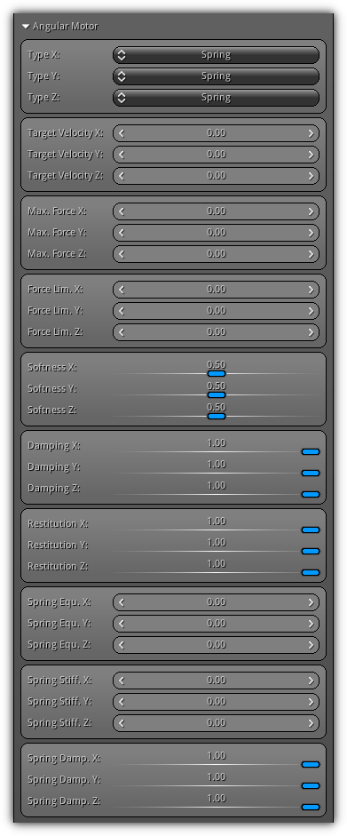
Type XYZ: Specify the type of angular motor to use for each axis; select between None, Motor or Spring for each axis.
Target Velocity XYZ: The targeted angular velocity the motor will try to reach for each axis.
Max. Force XYZ: The maximum amount of angular force that should be applied on each axis.
Force Lim. XYZ: Constraint force to a specific limit for each axis.
Softness: Describes the percentage of limits where the movement is free, beyond this percentage, the angular limit is gradually reinforced until the hard limit of 1.0 (100%) is reached.
Damping: Improve the stability of low pass jitter making the constraint more stable.
Restitution: Control the "bounciness" of the constraint on each axis.
Spring Equ. XYZ: The angular spring motor equilibrium point.
Spring Stiff. XYZ: Control the amount of angular stiffness the spring motor will apply on each axis.
Spring Damp. XYZ: The spring damping value to use for each rotational axis to stabilize low pass jittering.
Constant Force Mix
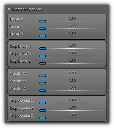
Linear XYZ: Control the linear constant force mix factor.
Stop Linear XYZ: Control the linear constant force mix factor when the constraint`s linear limits are reached.
Angular XYZ: Control the angular constant force mix factor.
Stop Angular XYZ: Control the angular constant force mix factor when the constraint`s linear limits are reached.
Error Reduction Parameters
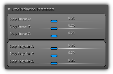
Stop Linear XYZ: Control the linear error reduction parameters when the constraint reached a linear limit.
Stop Angular XYZ: Control the angular error reduction parameters when the constraint reached an angular limit.
Soft Body Settings
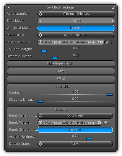
Aerodynamics: Determine the aerodynamic method that should be used to handle the active soft body physics. The method selected will affect how to solve contacts and penetration. Methods using vertex normals are more accurate but computationally more intensive than the one using face normals. Take note if you need to simulate flying objects you need to select a type that will take into consideration the Lift and Drag forces. In addition, a method that are using vertex normals are more accurate but also more computationally expensive than the one using face normals.
| Aerodynamics | Description |
|---|---|
| Vertex Normal | Vertex normals are taken as it is. |
| VNormal Oriented | Vertex normals are oriented toward velocity. |
| VNormal Flipped | Vertex normals are flipped to match velocity. |
| VNormal Flipped+Lift+Drag | Vertex normals are flipped to match velocity and lift and drag forces are applied. |
| Face Normal | Face normals are taken as it is. |
| FNormal Flipped | Face normals are flipped to match velocity |
| FNormal Flipped+Lift+Drag | Face normals are flipped to match velocity and lift and drag forces are applied. |
Total Mass: Specify the total mass of the soft body.
Weighted: Force the mass to be evenly spread among the nodes that form the soft body. It is recommended to consider the actual mass of each node (one node per vertex) and ensure their values are greater or equal to 0.1 to ensure stability. If turned off the Mass represent the mass value that will be applied for each node.
Primitive(s): Select a primitive to affect its PhysicMaterial.
Physic Material: The active primitive physic material. To assign one press the ![]() button to populate the list of all existing physic materials; select an entry to confirm. To cancel your selection and detach the physic material from the active primitive press the
button to populate the list of all existing physic materials; select an entry to confirm. To cancel your selection and detach the physic material from the active primitive press the ![]() button. The
button. The ![]() value display the number of active reference to the selected physic material.
value display the number of active reference to the selected physic material.
Collision Margin: Create an invisible border around the physic object to prevent soft body object to pass through other physics entities. Take note usually, this value has to be higher than the one you usually set for rigid bodies.
Dynamic Friction: The friction factor that will control how much the soft body will "slide".
- Note
- To enable or disable physic material callbacks for the active soft body toggle on/off the
 button.
Anisotropic Friction
Coefficient XYZ: Controls the internal friction damping by altering the value for each axis; like this, you can control the impact of friction on a per axis basis (this vector is always relative to the friction direction vector).
Gravity
Vector XYZ: Allow you to specify a custom gravity vector for the active soft body. A vector value of 0,0,0 tells the system to use the standard gravity vector set up in the World properties.
Wind
Velocity XYZ: Similar as for Gravity these fields allow you to set a custom wind velocity that will only affect the active soft body. If the vector value is set to 0,0,0 the soft body will respond to the wind velocity set up in the World properties.
Thresholds
Concat: Specify the amount of time in second (where 1.0 = 1 sec.) before the soft body contact point is considered resting; allowing the soft body to be deactivated.
Sleeping Linear: The amount of time the active velocity should be considered as stable to allow the soft body to be deactivated.
Options
Bend. Constraints: Precalculate bending constraints of the active soft body topology ( ensure the geometry is in rest mode before toggling this option). Select between None which will cause the soft body nodes to be fully bendable and will show no resistance; Optimized or Generic to simulate more bouncy/jelly-like objects.
Bend. Material: The physic material to use while generating bending constraints.
Rand. Constraints: Randomize the bending constraints to make to object more lifelike.
Anchor Hardness: Generic setting that dictates how anchor constraints behave. A value near 0 makes the soft body very elastic; a value of 1 makes it more stiffed.
Default State: The default activation state of the soft body that will be applied at creation time. Select between Active, Deactivated which will put the physic object on standby, Disable Deactivation forcing the physic object to stay alive or Disable Simulation which will cause the physic object to be excluded from the physic simulation.
Volume Settings
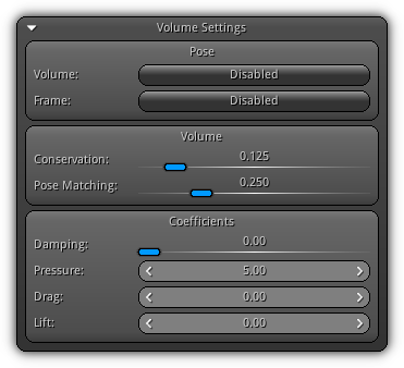
The following settings deal strictly on how the soft body will react to collision impact and behave under certain conditions. The parameters that you can set below you can either make the soft body react like a piece of paper or like a tick piece of jello.
Pose
Volume: Snapshot the volume allowing the soft body to come back to its original volume.
Frame: Snapshot the vertex position allowing the soft body to come back to its original form.
Volume
Conservation: Upon impact how much percentage of the original volume should be kept.
Pose Matching: How much percent the volume can be deformed compare to its original pose.
Coefficient
Damping: How much the environment affect the soft body. A value of 0 represents that the air has very little impact, while a value of 1 represents full impact.
Pressure: A value (either positive or negative) that represent the amount of pressure to apply on the soft body.
Drag: The drag force coefficient to apply on the soft body.
Lift: The lift force coefficients that affect the active soft body.
- Note
- Drag and Lift forces are allowed only if the current
Aerodynamicsmethod selected are supporting them. In both cases, the value to apply will vary depending on the soft body mass.
Collision Settings
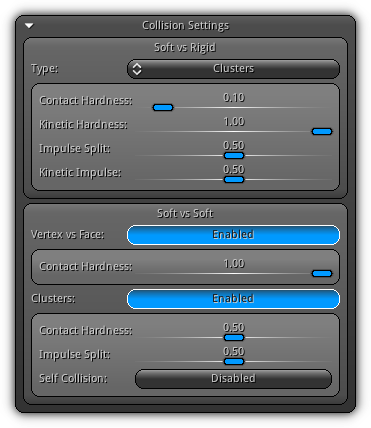
In this section, you will be controlling how the collision between soft body vs soft body and soft body vs rigid body is handled. Based on the type of object, you are trying to simulate choose an appropriate combination that will give you enough realism and good performances.
Soft vs Rigid
Type: Select between None which disable collision with rigid bodies; Sign Dist. Field (signed distance field) which gives good performances; and Clusters more computationally expensive but more precise (and tweakable).
Concat Hardness: Rigid contact hardness.
Kinetic Hardness: Rigid kinetic hardness.
Impulse Split: Soft vs rigid impulse split (cluster only).
Kinetic Impulse: Soft vs rigid kinetic impulse (cluster only).
Soft vs Soft
Vertex vs Face: Enable vertex vs face collision. If disabled face vs face will be used.
Contact Hardness: Soft contact hardness.
Clusters: Enable soft vs soft clusters collision; which is more accurate but more CPU extensive.
Concat Hardness: Soft vs soft clusters contact hardness.
Impulse Split: Soft vs soft clusters impulse split.
Self Collision: Enable or disable clusters self collision (clusters only); more realistic but more CPU extensive.
Misc. Settings
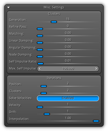
The following properties allow you to manually set various parameters
to either improve the performance of precision for the active soft body your preferences.
Clusters
Generation: The cluster size to use; the higher the more precision you will get at the cost of more CPU usage.
Refine Pass: The more pass the more refined the clusters will generated.
Matching: The percentage the clusters should match the original geometry topology.
Linear Damping: Amount of linear damping the clusters should be using.
Angular Damping: Amount of angular damping the clusters should be using.
Node Damping: Amount of damping cluster nodes should be using.
Self Impulse Ratio: Available only when clusters self-collision is enabled; this value controls the impact on nearby clusters.
Max. Self Impulse: Set the maximum amount of impulse ratio.
Iterations
This section can drastically improve performances; only apply the minimum "acceptable" amount of iterations that keep your soft body stable for best performances. All default values set here are set to work for cases; tweak each of them to either optimize your soft body for performance (fewer iterations) or precision (more iterations).
Position: Specify the amount of position iterations.
Clusters: Available only when soft cluster collision is enabled. This value control how many iterations should be used on clusters.
Solve Velocities: Enable velocity solver.
Velocity: Amounts of iterations the velocity solver will execute.
Drift: A value greater than 0 will enable the solver to also process the drift.
Interpolation: Available only if drift solving is enabled (see above). Increase this value to have smoother drift interpolation.
- Note
- Each iteration are effectuated on a per frame basis as long as your soft body is activated.
Soft Body Constraints
Soft Body constraints allow you to easily create connections between existing soft and rigid bodies or limit the movement of particular nodes.
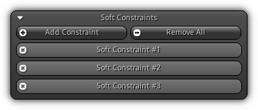
Add Constraint: Press the button to populate the list of all available constraint type. Select one to create it; refer to the Constraints Types table below to learn more about each them. Once added the constraint will appear on the list (as shown in the image above). To remove an existing constraint press the ![]() button located on the left side of the associated slot box.
button located on the left side of the associated slot box.
Remove All: Clear all soft constraints attached to the active soft body.
Constraints Types
| Type | Description |
|---|---|
| Pin | Pin the closest node to a static location by setting its mass to 0. 
|
| Anchor | Create a point to point constraint either in soft body local space or relative to an existing rigid body. 
|
| Linear Joint | Available only when the active soft body is using clusters; this type of constraint creates a linear (movement only) joint between either a soft body or a rigid body. This type of joint will restrict the movement of the soft body. 
|
| Angular Joint | Available only when the active soft body is using clusters; this type of constraint creates an angular joint (rotation only) between either a soft body or a rigid body. This type of joint will restrict the rotational movements of the soft body to a specific axis. 
|
- Warning
- Joints are obsolete when velocity solving is enabled.
Settings
The properties enumerated below are common for all soft body constraints and represent the base settings for each constraint type.
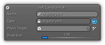
Name: A unique name to identify the soft body constraint.
Type: For reference only display the type of the active constraint. To enable or disable the constraint either enable or disable the checkbox ( ![]() ).
).
Physic Target: Allow you to connect another soft body or an existing physic object to the constraint. Take note in some case this term is replaced by Rigid Target which specify the target can only be an existing rigid body. Located on the right side the widget the ![]() button determine if the connected bodies should collide or not.
button determine if the connected bodies should collide or not.
Draw Size: Set the draw size for the constraint displayed in the View3d (edit mode only).
Pin
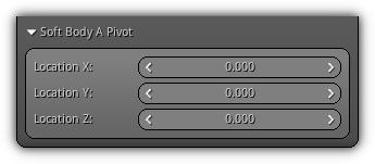
Soft Body A Pivot: Set the pin location; the XYZ value specified will automatically snap to the closest node and set its mass to 0 in order to prevent its movements in space.
Anchor
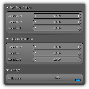
Soft Body A Pivot: Set the location XYZ of the attachment point of the anchor; the position specified will automatically snap to the nearest node.
Rigid Body B Pivot: If a rigid target has been specified the anchor location XYZ relative to the target transformation. Instead, the position will be relative to the soft body A transform.
Influence: Specify the influence (in term of percentage, 0.0 ~ 1.0) of the anchor on the active soft body.
Linear Joint

Soft Body A Pivot: Set the location XYZ of the first hook of the linear joint.
Rigid Body B Pivot: If a physic target has been specified the location XYZ will be relative to the target transformation. Instead, the position will be relative to the soft body A transform.
Force Mix: Constant force mix factor.
Error Reduction: Error reduction parameters.
Split Factor: The constraint impulse split factor.
Angular Joint
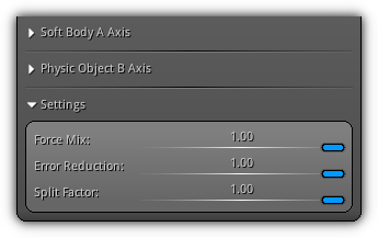
Soft Body A Axis: Specify the rotational axis in "soft body A" space.
Rigid Body B Pivot: If a physic object has been specified the rotational axis XYZ will be relative to the target transformation. Instead, the axis will be relative to the soft body A transform.
Force Mix: Constant force mix factor.
Error Reduction: Error reduction parameters.
Split Factor: The constraint impulse split factor.
|
|